


|
||||||
| Electronics | Audio | NAV | Infotainment Anything related to in-car electronics, navigation, and infotainment. |
 |
|
|
Thread Tools | Search this Thread |
 09-18-2013, 09:53 AM
|
#1 |
|
Frosty Carrot

Join Date: Jan 2013
Drives: The Atomic Carrot
Location: Baltimore, MD
Posts: 513
Thanks: 272
Thanked 431 Times in 199 Posts
Mentioned: 19 Post(s)
Tagged: 0 Thread(s)
|
Base Pioneer Radio Outputs
Howdy!
I have the base model 2013 Pioneer head unit, and I'm trying to decypher what outputs are available for use. Edited x2! Facts: - The RCA output can be turned on or off by enabling the subwoofer. - The RCA output are monaural. - The RCA output may not be manipulated with the fader, but the volume knob and low-pass filter do affect it. - The headunit outputs a high-level stereo signal to the rear fill speakers. This may have a high-pass filter built into the HU. - The headunit outputs a high-level stereo signal to the front door speakers. This does not appear to be filtered. - The rear amplifier (in the trunk) taps into the front door speaker signals. - The rear amplifier outputs 4 wires to each dash pod (tweeter + midrange). - The rear amplifier is a 2-way stereo crossover + amplifier with balanced inputs.
__________________
If you think you're nerd enough, join in the discussions about Suspension and Aerodynamic modelling!
Wall of Fame - JDL Auto Design, Raceseng, Vishnu Tuning, Penske Shocks, Nameless, Perrin, RaceComp Engineering, Essex/AP Racing, Verus, RacerX Wall of Shame - aFe Takeda, Wilwood, FA20Club Last edited by Shankenstein; 10-10-2013 at 11:32 PM. |

|

|
|
09-18-2013, 03:52 PM
|
#2 |
|
Frosty Carrot
Join Date: Jan 2013
Drives: The Atomic Carrot
Location: Baltimore, MD
Posts: 513
Thanks: 272
Thanked 431 Times in 199 Posts
Mentioned: 19 Post(s)
Tagged: 0 Thread(s)
|
Just had a great discussion with a coworker about car audio. Someone who isn't him may be a design engineer within the automotive amplifier division of a major audio company.
His advice was to NEVER use unbalanced (RCA) signals in cars. Since the signal is referencing the head unit's chassis ground, it's pretty likely that your amplifier/DSP is referencing a slightly different ground. Ground loops allow noise in. His suggestion was to use the speaker-level outputs to generate a "balanced" low level output. This uses a "differential attenuator" circuit that is pretty simple: 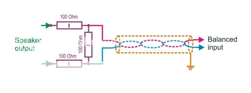 According to the Scion/Pioneer manual, our speaker outputs are 40W maximum. Speakers are a nominal 4 Ohm impedance. P = V * I = V^2 / R 40 = V^2 / 4 Vmax = sqrt(10) = 3.162 Volts Vrms = Vmax / sqrt(2) = 2.236 Volts If I'm plugging into a MiniDSP: LINK to manual The maximum input Vrms is 8. That means we don't have to attenuate the signal. One more consideration should be made. Amplifiers can deliver mild amounts of DC offset, which are fine when you're driving a speaker... but not fine when that's sent through a DSP and amplifier. To remove DC offset, you need to decouple the headunit from the DSP using a capacitor. If the input impedance on the DSP is 48 kOhms (like on the MiniDSP), you can determine how much (or little) this capacitor will affect the signal. LINK to Calculator A $1 bipolar electrolytic capacitor from Mouser, with capacitance of 100 uF will have a corner frequency of ~0.03 Hz. At -20dB/decade, that's atleast -50dB of floor below a 20Hz signal. TL;DR - Don't use unbalanced RCA's if SQ is your target. Speaker-level outputs are balanced, but you might need to attenuate and adjust for offset.
__________________
If you think you're nerd enough, join in the discussions about Suspension and Aerodynamic modelling!
Wall of Fame - JDL Auto Design, Raceseng, Vishnu Tuning, Penske Shocks, Nameless, Perrin, RaceComp Engineering, Essex/AP Racing, Verus, RacerX Wall of Shame - aFe Takeda, Wilwood, FA20Club |
|
|
|
| The Following User Says Thank You to Shankenstein For This Useful Post: | AtlasMick (09-23-2013) |
|
09-22-2013, 11:23 PM
|
#3 |
|
Frosty Carrot
Join Date: Jan 2013
Drives: The Atomic Carrot
Location: Baltimore, MD
Posts: 513
Thanks: 272
Thanked 431 Times in 199 Posts
Mentioned: 19 Post(s)
Tagged: 0 Thread(s)
|
From the last few days of research, there are quite a few amplifiers that accept balanced inputs.
Rockford Fosgate Power series Kicker ZX series Hifonics Brutus and Zeus serieses JL Slash and XD serieses Alpine PDX series Image Dynamics Q series Cerwin Vega "Vega" series Infinity Kappa series Orion XTR series Soundstream Reference series There are some high end amps like Audison, Zapco, Xtant, etc. Out of my price range ,and most modern (A/B) amps are clean enough to never be the bottleneck in a car environment... if they're set up and driven properly. Now to find a combination of power levels and channels that will get er done.
__________________
If you think you're nerd enough, join in the discussions about Suspension and Aerodynamic modelling!
Wall of Fame - JDL Auto Design, Raceseng, Vishnu Tuning, Penske Shocks, Nameless, Perrin, RaceComp Engineering, Essex/AP Racing, Verus, RacerX Wall of Shame - aFe Takeda, Wilwood, FA20Club Last edited by Shankenstein; 09-23-2013 at 12:10 AM. |
|
|
|
|
09-25-2013, 04:30 PM
|
#4 |
|
Frosty Carrot
Join Date: Jan 2013
Drives: The Atomic Carrot
Location: Baltimore, MD
Posts: 513
Thanks: 272
Thanked 431 Times in 199 Posts
Mentioned: 19 Post(s)
Tagged: 0 Thread(s)
|
Power Requirements:
The woofer is usually the limiting factor with 60 Wrms @ 4 ohm with 88 dB @ 1W @ 1m Final output = 88 dB + 3 dB * log_2 (60) = 88 + 3 * ~6 = ~106 dB To match the woofers, our midranges will require: W = 1 * 2^( 1/3 * (106 dB - 91 dB/W/m) ) = 2^(15/3) = 2^5 = 32 Watts (per midrange) @ 8 ohms To match the woofers, our tweeters will require: W = 1 * 2^( 1/3 * (106 dB - 91 dB/W/m) ) = 2^(15/3) = 2^5 = 32 Watts (per tweeter) @ 4 ohms For Hifonics, that means: ZRX600.4 + ZRX500.2 = $100 + 89 = $189 S/N Ratio = 90 dB For Orion: XTR600.4 + XTR250.2 = $170 + $115 = $285 S/N Ratio = 95 dB For Kicker: 11ZX3504 + 11ZX200.2 = $180 + $120 = $300 S/N Ratio = 91 dB For Rockford Fosgate: T400-4 + T400-2 = $240 + $240 = $480 S/N Ratio = 85 dB For Alpine PDX-F4 + ??? = $309 S/N Ratio = 94 dB Infinity Kappa Four + = $280 + S/N = 85 dB JL XD600/6 = $350 S/N Ratio = 104 dB Cerwin Vega VEGA500.4 + VEGA250.2 = $164 + $110 = $275 S/N Ratio = 90 dB Soundstream REVF4.400 + REF2.370 = $190 + $160 = $350 S/N Ratio = 102 dB Precision Power PC400.4 + PC360.2 = $150 + $130 = $280 I'll fill the list out more fully tonight. There's also a spreadsheet that is detailing the install components. It will be useful in determining how much sleeving, heat shrink, wire, connectors, etc. This project needs to go properly, so it won't be "back of the napkin" anymore. https://docs.google.com/file/d/0B1fR...4zMl9KajQ/edit
__________________
If you think you're nerd enough, join in the discussions about Suspension and Aerodynamic modelling!
Wall of Fame - JDL Auto Design, Raceseng, Vishnu Tuning, Penske Shocks, Nameless, Perrin, RaceComp Engineering, Essex/AP Racing, Verus, RacerX Wall of Shame - aFe Takeda, Wilwood, FA20Club Last edited by Shankenstein; 10-17-2013 at 09:42 AM. |
|
|
|
|
09-26-2013, 10:32 PM
|
#5 |
|
Frosty Carrot
Join Date: Jan 2013
Drives: The Atomic Carrot
Location: Baltimore, MD
Posts: 513
Thanks: 272
Thanked 431 Times in 199 Posts
Mentioned: 19 Post(s)
Tagged: 0 Thread(s)
|
There's already an awesome thread detailing a tweak for the BRZ EQ. That's not the point of this discussion. I'm trying to learn about RTA and microphone-based EQ for tuning a DSP.
There's a software package (fancy Java script that interacts with audio devices) called "Room EQ Wizard" or REW. You can download it: HERE after registering with the forums. If anybody is lazy or paranoid, I'll send you the file. Configuration: The basic premise is that you have a sound card. It isn't quite perfect, since there is an inherent delay and some noise/filters/etc that color the outputs and inputs. You hook up a "loopback" which connects the line out (or headphone) to line in (or microphone) and quantifies the the deficiencies in a calibration file. SPL Meter: Once your sound card is calibrated, you can set up a microphone. The microphone level needs to be adjusted to accurately reflect the sound pressure level (SPL). After a gain-match, the software will be good to go.  RTA: From here, you can send a wide range of signals (sweeps, noise, tones, etc) and monitor the frequency spectrum using the RTA feature. You may have to zoom out or in, to see the frequencies you're interested in... but it's fairly accurate (though there is some lag). Using a white noise tone, you should be able to see the baseline response of the room/cabin/etc. With some tweaking of the EQ, you can flatten the response.  Delay: Using impulse signals (and a properly calibrated microphone and sound card) you can get a ball-park figure for system delays. Different frequencies are produced by different speakers... which are located closer or further from your ears (or a microphone). They will arrive at different times and this can manifest as destructive interference and cognative dissonance (it just doesn't sound good, psychoacoustically). If your head unit or DSP has a delay or time align feature... use it to dial in the impulse response throughout the frequency range. Waterfall plots are useful in determining reflections and reverberations. You can do those too, which may be quite relevant for decyphering an automotive cabin.  The final step is to fiddle with crossover frequencies, roll-off rates, and individual speaker EQs. This is an iterative process, but determining the usable frequency range of each speaker is important. If there's significant overlap, decide which speaker is best suited to the instrument/sound that a frequency is used. It's trial-and-error mixed with personal preference. I'll update the thread with my own opinions once I get some (opinions).
__________________
If you think you're nerd enough, join in the discussions about Suspension and Aerodynamic modelling!
Wall of Fame - JDL Auto Design, Raceseng, Vishnu Tuning, Penske Shocks, Nameless, Perrin, RaceComp Engineering, Essex/AP Racing, Verus, RacerX Wall of Shame - aFe Takeda, Wilwood, FA20Club |
|
|
|
| The Following User Says Thank You to Shankenstein For This Useful Post: | mid_life_crisis (10-11-2013) |
|
09-27-2013, 10:32 PM
|
#6 |
|
Frosty Carrot
Join Date: Jan 2013
Drives: The Atomic Carrot
Location: Baltimore, MD
Posts: 513
Thanks: 272
Thanked 431 Times in 199 Posts
Mentioned: 19 Post(s)
Tagged: 0 Thread(s)
|
 DC-DC Buck-Boost Converter: this is a "DC-DC-USB-200" from Mini-Box who were gloriously fast with their processing and shipping. The output is 12V steady, and will accept 8 - 32 Vdc. Current rating is ~10 A. It has an Automotive Mode which will automatically shut down when battery voltage drops too low (11.4 V under steady drain), and can delay turn-off to prevent thumps and allow for cooldown. Mini-DSP: 2x8 Main board, Front Panel, Digital Panel, USB front Panel, U-MIK 2x8 main board: note the unbalanced RCAs, euroblock balanced inputs, and tasty tasty ICs (mmmm... chips... *drool* ) Front Panel: this houses a master volume knob (huge) and allows you to select between configurations. This will be great when demoing. You can retune the DSP to a passenger seat configuration with one click. Digital Panel: This allows for coaxial (SPDIF) inputs and TOSLINK optical inputs. They threw in 2 optical cables too (fiber is the future!). Speakers: Dayton RS180 7" + RS52 2" + Vifa XT25SC 1" are carry-over from previous projects (see the chipped paint) but all sound phenomenal. Time to setup the laptop with Room EQ Wizard and configure the UMIK. It shant be said that OP failed to deliver. :happy0180:
__________________
If you think you're nerd enough, join in the discussions about Suspension and Aerodynamic modelling!
Wall of Fame - JDL Auto Design, Raceseng, Vishnu Tuning, Penske Shocks, Nameless, Perrin, RaceComp Engineering, Essex/AP Racing, Verus, RacerX Wall of Shame - aFe Takeda, Wilwood, FA20Club |
|
|
|
|
09-28-2013, 06:31 PM
|
#7 |
|
Frosty Carrot
Join Date: Jan 2013
Drives: The Atomic Carrot
Location: Baltimore, MD
Posts: 513
Thanks: 272
Thanked 431 Times in 199 Posts
Mentioned: 19 Post(s)
Tagged: 0 Thread(s)
|
Do work, son!
Power Ring will attach to the battery. 1/0 AWG stranded copper welding wire is used up to the distribution blocks. High current DC is effectively stick welding, and there's too much hype (and price gouging) surrounding the copper-clad aluminum and similar hybrid power wires. Audiopipe may not be the highest end, but their power equipment is Stinger-grade. 2 x 900 Wrms for sub amps (@ 90% full tilt efficiency) + 6 x 60 Wrms for lows-mids-highs (@ 60% full tilt efficiency) + 10 Wrms for DSP (@ 90% efficiency). That's 240 Amps if the system drops to 11 V. A little headroom is fine, since any serious short will trip the breaker. Water-tight and ready for action. Distributing to two circuit breakers. The 150 A is for 6 channels of low-mid-high + DSP. The 200 A is for both sub amps. Laid out and including fuses (< 12" from each amplifier). Big picture, with the DSP, ground wires, amps, and signal routing. Lots of parts to go... but it's coming together nicely. Steps remaining: - Build a breakout harness for the factory amp. Never to cut wires if there's an option. - Fuse holders - Main amps - Mini-DSP configuring - Mini-DSP housing and connectors - Install everything
__________________
If you think you're nerd enough, join in the discussions about Suspension and Aerodynamic modelling!
Wall of Fame - JDL Auto Design, Raceseng, Vishnu Tuning, Penske Shocks, Nameless, Perrin, RaceComp Engineering, Essex/AP Racing, Verus, RacerX Wall of Shame - aFe Takeda, Wilwood, FA20Club Last edited by Shankenstein; 09-28-2013 at 06:42 PM. |
|
|
|
|
10-10-2013, 10:34 PM
|
#8 |
|
Frosty Carrot
Join Date: Jan 2013
Drives: The Atomic Carrot
Location: Baltimore, MD
Posts: 513
Thanks: 272
Thanked 431 Times in 199 Posts
Mentioned: 19 Post(s)
Tagged: 0 Thread(s)
|
Eventually I'll turn this into a build log, but for now it's a great sandbox for idea dumping. Hopefully someone will find it useful.
Super thanks to @RandomHero and his pinout sleuthing. LINK I'm doing something different: My Metra harnesses came in this week (one male, one female). They look like this:  The pinout for the headunit is: where D13: 1 = Right Rear + 2 = Left Rear + 3 = Right Rear - 4 = ----- 5 = ----- 6 = Left Rear - D14: 1 = Right Front + 2 = Left Front + 3 = Accessory Power (IGN or VBAT) w/ 7.5 A upstream fuse 4 = Keep Alive Power (KAPOWER) w/ 20 A upstream fuse 5 = Right Front - 6 = Left Front - 7 = Ground 8 = Antenna 9 = Rear Amp Turn-on 10 = ----- I only really care about D14 and it's #1, 2, 4, 5, 6, 7, 9 wires. - Wires #2 & 6 will go into a shielded twisted pair. This is the left channel input to the DSP. - Wires #1 & 5 will go into a shielded twisted pair. This is the right channel input to the DSP. - Wires #4, 7, & 9 will go into a relay. This will be the "remote" trigger for all equipment. Relay pin structure is the traditional:  where Wire #4 --> Pin 30 Wire #7 --> Pin 85 Wire #9 --> Pin 86 (I hear that an 86 is a big turn on... amirite guyz?) Remote trigger --> Pin 87 The shield on both signal wires will be grounded at the DSP. Ground loops are no bueno, which is why you ground the shield on one end only. Now we've got everything in line for the breakout harness and turn-on circuitry. Where to mount the power distribution, DSP, and amps... suggestions?
__________________
If you think you're nerd enough, join in the discussions about Suspension and Aerodynamic modelling!
Wall of Fame - JDL Auto Design, Raceseng, Vishnu Tuning, Penske Shocks, Nameless, Perrin, RaceComp Engineering, Essex/AP Racing, Verus, RacerX Wall of Shame - aFe Takeda, Wilwood, FA20Club |
|
|
|
|
11-17-2013, 11:53 PM
|
#9 |
|
Frosty Carrot
Join Date: Jan 2013
Drives: The Atomic Carrot
Location: Baltimore, MD
Posts: 513
Thanks: 272
Thanked 431 Times in 199 Posts
Mentioned: 19 Post(s)
Tagged: 0 Thread(s)
|
Thread Revival. The breakout harness has been made and so has the amp selection.
I chose to go with Precision Power (PPI) and a pair of PC640.4 amps. 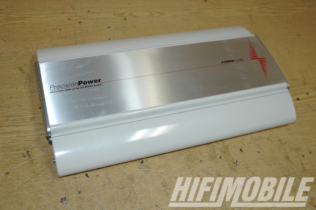 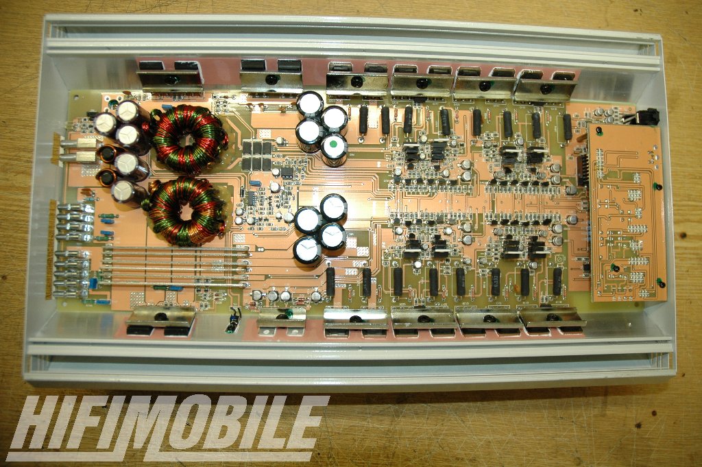 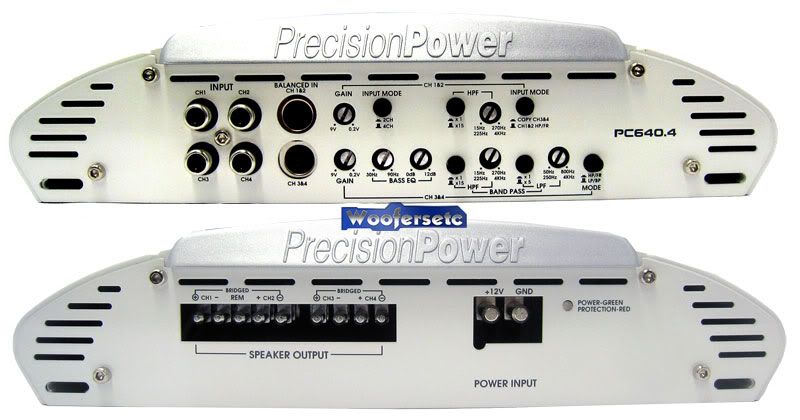 4 ch. Class A/B RMS Power 4Ω = 115 x 4 RMS Power 2Ω = 160 x 4 RMS Power 4Ω Bridged = 320 x 2 Damping Factor > 3000 Stereo Separation = 68dB Balanced inputs (via 6-pin mini-DIN aka PS/2 plug) They have a long history of solid amps, and the recent come-back with the Phantom series (and the active support on DIYMA) lend alot of credibility. It's also obvious from their ads that they aren't marketing to meatheads. Tolerances on components and details about amplifier stage architecture really get it done for me. These amps will get toasty and may not have the latest in efficient technology... but they didn't cut any corners in the places that it matters. Plus with a huge amount of overhead, they should stay frosty. To compliment the amps, I'll need to create some cables. The DSP will output 8 XLR plugs, and those will snake into 4 mini-DIN plugs at the amps. The pinout is: 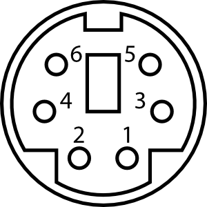 Pinout: 1 = Phantom Power - 2 = Phantom Power + 3 = Left - 4 = Right- 5 = Left + 6 = Right + Shield = ground In this configuration, the shielding has to be tied (which generally isn't kosher) but it's as close as I can get to perfection. I will look into a strain-relief method for the mini-DIN connectors, since they don't "lock" in and occasionally have been known to fall out during vigorous driving.
__________________
If you think you're nerd enough, join in the discussions about Suspension and Aerodynamic modelling!
Wall of Fame - JDL Auto Design, Raceseng, Vishnu Tuning, Penske Shocks, Nameless, Perrin, RaceComp Engineering, Essex/AP Racing, Verus, RacerX Wall of Shame - aFe Takeda, Wilwood, FA20Club Last edited by Shankenstein; 05-19-2015 at 02:25 PM. |
|
|
|
|
12-11-2013, 12:53 PM
|
#10 |
|
Frosty Carrot
Join Date: Jan 2013
Drives: The Atomic Carrot
Location: Baltimore, MD
Posts: 513
Thanks: 272
Thanked 431 Times in 199 Posts
Mentioned: 19 Post(s)
Tagged: 0 Thread(s)
|
Built some cables this weekend. The inventory is:
1 x OEM harness breakout --> cable --> 2 female XLR connectors 2 x XLR male jack --> cable --> 3-pin phoenix block (balanced input for MiniDSP) 2 x 12-pin phoenix block (balanced outputs for MiniDSP) --> cable --> 4 XLR female jacks 2 x 2 XLR male connectors --> cable --> PS/2 (6-pin mini DIN) male connector (balanced input for PC640.4) Cable is microphone cable (2 conductor, braided copper shield) from Monoprice. Connectors/jacks are solder-cup units from GLS Audio. PS/2 connectors are from Belkin patch cables. Heat shrink is from a Harbor Freight value pack. Oh, and winter is coming...
__________________
If you think you're nerd enough, join in the discussions about Suspension and Aerodynamic modelling!
Wall of Fame - JDL Auto Design, Raceseng, Vishnu Tuning, Penske Shocks, Nameless, Perrin, RaceComp Engineering, Essex/AP Racing, Verus, RacerX Wall of Shame - aFe Takeda, Wilwood, FA20Club |
|
|
|
|
12-11-2013, 01:26 PM
|
#11 |
|
Senior Member
Join Date: May 2013
Drives: FR-S 10 #103 AT
Location: NC
Posts: 1,519
Thanks: 101
Thanked 599 Times in 347 Posts
Mentioned: 5 Post(s)
Tagged: 0 Thread(s)
|
I'm thinking about using a MiniDSP myself, so I'm following this with interest.
Good work so far.
__________________
Necessity may be the mother of Invention but Desperation is quite often the father.
Sex is like Bridge. If you don't have a good partner, you'd better have a good hand. - Mae West Papa said, "son there's a lot of evil temptations out there. Best to try 'em all so you know which ones to avoid." |
|
|
|
| The Following User Says Thank You to mid_life_crisis For This Useful Post: | Shankenstein (12-11-2013) |
|
12-11-2013, 08:09 PM
|
#12 | |
|
Frosty Carrot
Join Date: Jan 2013
Drives: The Atomic Carrot
Location: Baltimore, MD
Posts: 513
Thanks: 272
Thanked 431 Times in 199 Posts
Mentioned: 19 Post(s)
Tagged: 0 Thread(s)
|
Quote:
Got the 10x10 plug-in running on Tuesday. Super easy to use. Highly recommended. Step 1: EQ the inputs to correct for issues with the source. You control frequency, gain (magnitude) and Q (steepness). Step 2: Route the signals (Analog Input 1 --> Analog Outputs 1, 3, 5, 7) Step 3: Set the high- and low-pass crossover frequencies and rate\type for each channel. Step 4: Set time alignment (delay) based on the furthest speaker. Step 5: EQ the outputs to correct for issues with the speaker, enclosure, and cabin. Store up to 4 configurations and flash the DSP. If you get the front-panel the configurations can be selected from the driver's seat. Some plug-ins let you adjust the system in real-time, and most now let you do automatic EQ (like Bose, Alpine, Clarion have) if you run Room EQ Wizard from a laptop with a calibrated microphone and soundcard.  
__________________
If you think you're nerd enough, join in the discussions about Suspension and Aerodynamic modelling!
Wall of Fame - JDL Auto Design, Raceseng, Vishnu Tuning, Penske Shocks, Nameless, Perrin, RaceComp Engineering, Essex/AP Racing, Verus, RacerX Wall of Shame - aFe Takeda, Wilwood, FA20Club |
|
|
|
|
|
12-11-2013, 10:26 PM
|
#13 |
|
Senior Member
Join Date: May 2013
Drives: FR-S 10 #103 AT
Location: NC
Posts: 1,519
Thanks: 101
Thanked 599 Times in 347 Posts
Mentioned: 5 Post(s)
Tagged: 0 Thread(s)
|
This definitely works best with a multiple amp system. In my case it will just be two, primary and sub. I'll use the equalizer plugin most likely.
__________________
Necessity may be the mother of Invention but Desperation is quite often the father.
Sex is like Bridge. If you don't have a good partner, you'd better have a good hand. - Mae West Papa said, "son there's a lot of evil temptations out there. Best to try 'em all so you know which ones to avoid." |
|
|
|
|
|
|
|
|
|
|
 Similar Threads
|
||||
| Thread | Thread Starter | Forum | Replies | Last Post |
| FRS Stock Pioneer radio RCA outputs | mit_peid | Electronics | Audio | NAV | Infotainment | 7 | 10-09-2015 01:08 AM |
| Base Unit FR-S Pioneer stereo deck | rikdrt1 | Audio/Visual, Electronics, Infotainment, NAV | 0 | 12-04-2012 02:21 AM |
| FR-S Base Pioneer Radio w/iPhone | Boxer-86 | Electronics | Audio | NAV | Infotainment | 7 | 10-06-2012 04:38 PM |
| FR-S Pioneer Base Unit with bluetooth phone | NMMI89 | Electronics | Audio | NAV | Infotainment | 4 | 09-19-2012 12:11 AM |
| FR-S Base Radio ASL and ASR? | DjDATZ | Scion FR-S / Toyota 86 GT86 General Forum | 7 | 08-26-2012 12:45 PM |


