


|
||||||
| Suspension | Chassis | Brakes -- Sponsored by 949 Racing Relating to suspension, chassis, and brakes. Sponsored by 949 Racing. |
 |
|
|
Thread Tools | Search this Thread |
 04-03-2013, 02:35 AM
|
#1 |
|
Senior Member
Join Date: Nov 2012
Drives: Subarus
Location: Nowhere
Posts: 189
Thanks: 20
Thanked 129 Times in 66 Posts
Mentioned: 4 Post(s)
Tagged: 0 Thread(s)
|
Truths and Myths about Materials and Aerodynamics
*DISCLAIMER* This is a bit of a rant and reflect my opinion and my opinion alone. I am not talking about any single company or product in particular, but the industry in general. I understand companies have a need to market their products, what I don't like is false buzz words, claims, and leading customers on to make false assumptions on their own. I am not a materials or aerospace/fluids guy so I may be wrong on some aspects. However, I will try to make this as informative as possible to clear the air. Fact checks are welcomed and appreciated.
First, with composites. What is a composite? It is anything made of separate parts or elements. This means something as simple as a block of wood and a metal screw is a composite. In material science, it refers to any material made up of two or more parts. Composites allow one to utilize the strengths (and weaknesses) of both materials. Carbon fiber alone is a cloth, this is not a composite. It is typically mixed with an epoxy, which when cured, allows carbon fiber to hold a shape. That is why it is commonly called CFRP or carbon fiber reinforced plastic. So what is "dry carbon?" This is a HUGE marketing gimmick. I am still unsure as to what dry carbon really is. Go and feel your fancy carbon fiber part, it's dry right? If your carbon fiber is still wet, it's not fully cured. I am led to assume it is pre-prepregnated carbon fiber, but I cannot be certain. What is pre-pregnated carbon fiber? Pre-impregnated carbon fiber or pre-preg for short, is carbon fiber that comes with the epoxy already applied to the sheet. This allows for the most consistency without the need to apply epoxy. This is important because too little epoxy and the part may not be able to hold its structure. Too much epoxy and the part becomes heavier than necessary. Pre-preg is still tacky and I would consider it "wet" so the term "dry" does not make much sense to me. You typically make a pre-preg part by laying it onto the mold and curing it in an autoclave. An autoclave is just a large pressure cooker. The pressure squeezes the excess epoxy (even pre-preg has excess epoxy) onto a cloth which will absorb the excess epoxy. The heat cures the part and when the epoxy takes set, it will retain that shape. This process is why pre-preg and autoclaved parts are expensive. This is about the highest quality CFRP part you can make (there are exceptions). You can also do a wet layup. This process is similar to backyard fiberglass projects. You lay out the carbon cloth on to an open mold, then mix the epoxy and brush it on. In order to avoid dry spots extra resin is typically applied, making the part fairly heavy. This is how a majority of the misc. carbon fiber parts are made. You can also do a vacuum infusion process with wet layups. This is where the mold is sealed with a vacuum hose to suck out excess resin on to an absorbing cloth. The consistency is not as great as pre-preg, but this is probably the best way to make CFRP parts for the DIY'ers since no expensive tooling or machines are necessary, other than an air compressor. Does vacuum infusion technically count as a "dry" carbon part because excess resin was removed? The carbon fiber is dry before it starts the process, unlike pre-preg. By the same account, Resin Transfer Method (RTM) could be considered "dry" carbon. RTM is a process where the epoxy is premeasured, heated and forced into the closed mold by compression. This reduces excess resin and due to the heat, it allows the part to cure quickly. It also allows for complex shapes. Due to the low cost and fast production times, this is how most OEM CFRP parts are made. Ford, Chevy, and Dodge used this technique for the body panels of the Shelby GT500KR, Corvette Z06/ZR1, and Viper ACR, respectively. Other closed mold techniques are trapped silicone and high pressure bladder molding. This allows for hollow shapes to be made with a consistent thickness. Carbon is laid in the mold and the mold pressurizes, forcing the product to take the shape of the mold. This is how a good CFRP intake charge pipe would be made. I hope that gives you a little insight on the truth about "dry" carbon. Last edited by EarlQHan; 04-16-2013 at 10:54 AM. |

|

|
|
04-03-2013, 02:35 AM
|
#2 |
|
Senior Member
Join Date: Nov 2012
Drives: Subarus
Location: Nowhere
Posts: 189
Thanks: 20
Thanked 129 Times in 66 Posts
Mentioned: 4 Post(s)
Tagged: 0 Thread(s)
|
Wind Tunnel Tested means nothing!
There, I said it. It may sound like blasphemy, but please stay with me. There are some companies out there that have fancy pictures of their products in a wind tunnel. So what does that tell us? That the product spent time in a wind tunnel. Nothing more, nothing less. Let me put it this way, if I took the SAT, does that qualify me to go to MIT? If I take the BAR, does that make me a lawyer? What is a wind tunnel? It is just a simulation. Since my friend and business partner is much more versed in aerodynamics than I, I have copied some of his material he put on our blog: Wind tunnels idealize temperature change, wind boundary layer, and the wake of other cars. Inaccuracies can occur from: 1. The rolling road system (assuming it has a rolling road at all) 2. Wall effects of the tunnel section 3. Deformation of the tires 4. Cornering conditions from steer and yaw 5. Sting interference from holding the model 6. Wheel lift is typically not measured in a tunnel 7. The model does not move, so the relative motion is not the same as real life. Wind tunnel data is precise, but has many sources of inaccuracy. Unfortunately, real world data is accurate, but is not precisely measured. Another issue with tunnel testing is scaling. If you use a scaled wind tunnel, you need to appropriately scale the model to get useful data. This is due to Reynolds numbers and Reynolds scaling (stuff I would need to brush up on to fully explain since it's been a while since I took fluid mechanics, I'm sure plucas will jump in to explain later). Notice this picture of a full scale car and how small the wind tunnel is: 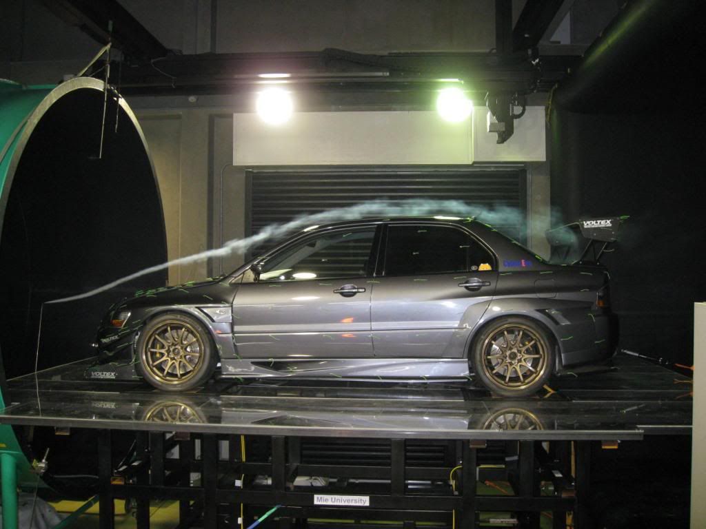 Now notice this picture and how the tunnel appears to be similar in size and how small the model is: 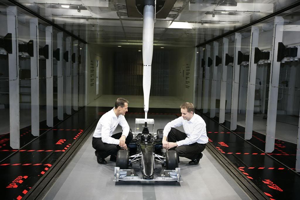 Now who's testing to trust? An aftermarket company that shares no results of its wind tunnel testing or Mercedes AMG F1? Another issue that arises with using a scaled tunnel scaled models are the scaled model must be that much more precise and the surface finish must be that much better. Now, does that mean the products don't work or aren't "aerodynamic?" It depends on your definition. Aerodynamics is the study of the motion of air and its interaction with objects. So, by that definition, anything that affects the flow of air is aerodynamic. This includes opening a window and sticking your hand out. Now, how effective and how efficient that part is must be quantified and tested through real life, wind tunnel, and CFD. Last edited by EarlQHan; 04-03-2013 at 03:19 AM. |
|
|
|
|
04-03-2013, 02:36 AM
|
#3 |
|
Senior Member
Join Date: Nov 2012
Drives: Subarus
Location: Nowhere
Posts: 189
Thanks: 20
Thanked 129 Times in 66 Posts
Mentioned: 4 Post(s)
Tagged: 0 Thread(s)
|
Everything is a spring: why your chassis and suspension links should be stiffness driven, not strength driven.
Anytime a force is exerted on an object, it deforms, no matter how small the force or the resulting deformation. There is no such thing as a perfectly rigid material. If you don't believe me, measure yourself as soon as you wake up and then measure yourself before you go to bed. You should be roughly 1" or 2.5 cm shorter at night than in the morning. This is because the force of gravity exerted on your body compresses your spine. First, there are a few engineering terms I will go over for those not familiar. Stress (sigma) - the uniaxial tensile force (F or P) divided by the original cross-sectional area (A naught) Strain (epsilon) - the ratio of the change in length (delta l) of the object in the direction of the applied force divided by the original length (l naught). Modulus of Elasticity (E) - an indication of the bond strength between atoms in the material. 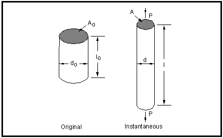 Using this example, the stress is P/A, the strain is (l-l0)/l0. Stress also equals strain times the modulus, so sigma = epsilon*E By testing the material, you determine the stress-strain curve.  The stress-strain curve tells you a few things about the material properties; it shows the yield strength, ultimate tensile strength (UTS or tensile strength for short), and the fracture point. Yield strength is the amount of stress a material can handle before it plastically deforms. Anything under the yield strength is the elastic deformation region. Elastic deformation is when an object will return to its original shape when the force is removed from the object. This is the equivalent of pressing on a spring, then removing your hand to let it return to its original length. Plastic deformation is when the material has deformed to such an extent, it cannot fully return to its original shape. The atoms have permanently been displaced and take up new positions. This is the equivalent of bending the tab on a paper clip so it becomes straight. The ultimate tensile strength is the maximum amount of stress the material can handle. After that point, if the cross-sectional area decreases (necking), it loses strength until fracture. Fracture is when the material breaks. To get an idea of strain and necking, stretch out a piece of gum, notice how it gets skinnier as it gets longer. This is due to something called Poisson's ratio. How much a material can elongate is referenced as ductility. Now, on to stiffness. Stiffness, k, is equal to the force, F, divided by displacement, x. It is also equal to the cross-sectional area, A, times the modulus, E, divided by length, l. So: k = F/x = AE/L So stiffness is determined by the material (modulus) and the design (area/length). The reason you want a stiffness-driven design over strength-driven is because a soft chassis or suspension link undergoes a lot of strain. Like a spring, this stores energy, rather than transferring it, meaning the steering and driver feedback is reduced and wildly varied, the loads are not transferred as they should, reducing grip and increasing lap times. If you think strength should drive these aspects, I will give you this example: a rubber band and a twig of the same weight can both support the same 5 lb (or 2.2 kg) load before breaking. So let's say you put a 4.4 lb (or 2 kg) load on both. The rubber band stretches to the ground, but doesn't break, the twig moves an amount imperceptible to the human eye, and also doesn't break. Now which would you prefer your suspension links and chassis to do? They're equally strong, but one is significantly stiffer. Last edited by EarlQHan; 04-19-2013 at 03:43 PM. |
|
|
|
| The Following User Says Thank You to EarlQHan For This Useful Post: | clzzical (04-26-2013) |
|
04-03-2013, 02:36 AM
|
#4 |
|
Senior Member
Join Date: Nov 2012
Drives: Subarus
Location: Nowhere
Posts: 189
Thanks: 20
Thanked 129 Times in 66 Posts
Mentioned: 4 Post(s)
Tagged: 0 Thread(s)
|
Unobtanium: How to select the appropriate materials for the job
If you read the above post and understand about stresses and strains, strength and stiffness, how do you determine the material? It largely depends on its application and the material properties, but the deciding factors should be stiffness-to-weight ratio (specific stiffness or modulus/density), strength-to-weight ratio (specific strength or UTS/density), overall strength, and fatigue strength. I will cover the most common motorsports materials, this is not meant to used as a material selection bible, but as a general guide. The numbers for each material were quickly grabbed off the internet, I have not verified the math exactly, but it should be in the ball park to be useful. First, you need to know the loading condition, so you know how the part will be stressed. Then you want to use a material that is stiff for that loading condition. Then you something that is strong enough to handle that load, repeatedly. COMPOSITE FIBERS The "it" material of the future. Extremely strong and light, it is the best material available. Or is it? Composite fibers work best in tension (being pulled), but okay in compression. Imagine using floss, if you pull on it, it's pretty strong, if you push, it folds. Fibers are typically weak in shear (imagine cutting it with shears). Therefore to best utilize the material, you must know the loading condition and orient the fibers in that direction. They have very good tensile strengths, specific strengths and specific stiffness. Carbon Fiber (70% fiber/30% matrix, unidirectional load along grain): Modulus: 181 GPa Yield strength: N/A Tensile strength: 1600 MPa Density: (yarn) 1.75 g/cc Specific strength: 914 Specific stiffness: 113 Carbon fiber has a very good specific strength (strength-to-weight), and if properly loaded, a great specific stiffness. Carbon fiber will also work great as a stressed skin (chassis), and frames and links because they work as tensioned members. In order to take advantage of carbon fiber, it is largely dependent on the layup schedule and orientation of the fibers, to ensure they act in pure tension/compression. However, carbon fiber is also brittle, so upon failure, it shatters in a most spectacular fashion. One way to get the maximum out of carbon fiber is using pultruded carbon fiber, which aligns the fibers in a very straight orientation so you can use it in the direction of loading. Due to big demands of carbon fiber from OEMS in the aerospace and automobile industry and relatively low supply, raw carbon fiber is expensive. It also requires a lot of labor to produce useful parts, further driving up the cost. Aramids: The most widely known aramid is Kevlar, a trade name owned by DuPont. Because there are so many variations of aramids, I have not put up any specific numbers. Similar to carbon fiber, it has a good specific strength and stiffness. Like carbon fiber, it largely depends on how it's used. It is slightly weaker than carbon, but also less dense than carbon fiber. It is tougher, less resistant to fracture, which is why it is used for things like ballistic shielding. I am unsure of pricing. Fiberglass (E-Glass): Modulus: 81 GPa Yield strength: N/A Tensile strength: 1500 MPa Density: 2.6 g/cc Specific strength: 577 Specific stiffness: 31 Fiberglass has very specific strength and a specific stiffness compared to metals. However, like all fibers, it depends on the layup schedule, but chopped strand is very common. This randomizes the fiber orientation, making it more normalized to load variations than typical carbon fiber or aramid. It is common and cheap, so it is widely available and used. METALS The choice material that got us from the stone age to here. It's been around for ages, so what's there to know? Steel = industrial age, aluminum = flight age, titanium = space age. So why stick with steel? Metals are large crystals. They are rarely used in raw elemental form and are alloyed (other elements are mixed to create a solid solution). This alters the material properties at the atomic level. The alloying elements' atoms will squeeze in between the voids in the base element's atoms. Then this solution is cooled, where metals will begin to form crystals (grains) as it becomes solid. Then the metal can be treated and is finally worked to form whatever shape you need it to. Metals can be strain hardened (cold-worked) which plastically deforms the metal grains to make it harder and forged which will re-orient the grains to make the product stronger. Steel and aluminum are often precipitation hardened, which is a heat-treatment that creates a dense and fine dispersion of precipitated particles in the metal matrix. This is also known as aging. Every step of this matters. The alloy, the rate of cooling, the treatment, and how it is worked will all affect the strength and hardness of the material. Therefore, even between the same exact alloy, there can be a wide variation in strength, however the modulus will be very similar between different alloys and tempers of the same material, so the stiffness does not change much. Because metals have free electrons, most are susceptible to corrosion. This is an electrochemical reaction due to thermodynamics, the orderly alloy structure wants to give off energy to the system, to return to a lower energy state. This is why most metals are found in an oxidized state in nature. The exceptions are noble metals such as gold, platinum, titanium which are extremely stable. While I am not exactly sure why, but I believe they have a full electron orbitals, so they don't have free electrons to give, but I am not a physicist, so I may be way off base. Alloy Steel (we'll go with the most common, normalized 4130): Modulus: 200 GPa Yield strength: 435 MPa Tensile strength: : 670 MPa Density: 7.85 g/cc Specific strength: 85 Specific stiffness: 25 One of the most common materials available. Steel is the foundation of modern society. Steel is mostly iron, some carbon for added strength and hardness, and a dash of alloying elements. Dependent on its cell structure, cooling, tempering, and working, you can have a tensile strength as low as 400 MPa to over 1600 MPa. 4130 is commonly used because it is cheap, ductile, easy to work and weld, and has good strength. This is why it is often the go-to material. However, alloy steels are susceptible to corrosion, which once starts, will continue to spread in the presence of oxygen. Aluminum Alloy (once again, the most common, 6061-T6): Modulus: 70 GPa Yield strength: 240 MPa Tensile strength: 300 MPa Density: 2.7 g/cc Specific strength: 111 Specific stiffness: 26 Aluminum, a very common material. Like steel the properties wildly vary between alloys and tempers. Aluminum is very low in density, making it great for low stress applications, such as stressed skins. That is why it is often mentioned as an aerospace alloy. 6061-T6 is used pretty much for all the same reasons as 4130. T6 indicates the material has been solution heat-treated and artificially aged. An added benefit to 6061-T6 is its corrosion resistance, making it more suitable for applications where moisture or salt are present. Aluminum, unlike steel, will form a thin oxide layer at the surface, which acts as a protective coating to prevent further oxidation. Magnesium Alloy (Elektron ZA): Modulus: 44 GPa Yield strength: 48 MPa Tensile strength: 170 MPa Density: 1.75 g/cc Specific strength: 97 Specific stiffness: 25 Magnesium is very common element. Its low density makes it the lightest structural metal available. Depending on the alloy, it can have excellent specific strength. However, due to its low yield, it is best used for low stress applications, unless the design envelope is large, like in the case of wheels. The problem is magnesium is highly reactive, and corrodes fairly rapidly, although new alloys are less susceptible. Another problem is magnesium is flammable which causes a chemical fire and cannot be put out with water. However, this is for small slivers; as a bulk material, it is much less likely to catch fire. Titanium Alloy (The most common structural alloy, 6Al-4V aka Grade 5): Modulus: 114 GPa Yield strength: 1100 MPa Tensile strength: 1170 MPa Density: 4.43 g/cc Specific strength: 264 Specific stiffness: 26 Titanium is incredibly difficult to produce (refine), making it very expensive. It has excellent specific strength, allowing you to make the parts very small, keeping it extremely light. This is why it is an excellent material to produce exhausts. It is also very stable, so corrosion is a non-issue. This is why it is a choice material for suspension links or stressed skins for those who can afford it. Now, notice for the metals the specific stiffness is nearly identical to all four alloys. That means they all have the same stiffness-to-weight ratio. Does this mean they are all equally stiff? Yes and no. Remember, k = AE/L. So it depends on the cross-sectional area and length. So, now to do an example (I am going to use metric for simplicity, we Americans should join the rest of the world and get on this system, it's quite convenient): Let's say if you want to design a suspension component, the hard points are determined by the chassis, let's say 30 cm. The suspension part only needs to handle 10 kN of load, and with a Factor of Safety of 1.5, let's say it is built to withstand 15 KN (a strength driven design). 4130: stress = 435 MPa A = .345 cm^2 V = 10.35 cc m = 81 g k = 23 kN/mm 6061: stress = 240 MPa A = .625 cm^2 V = 18.75 cc m = 51 g k = 14.6 kN/mm ZA: stress = 48 MPa A = 3125 cm^2 V = 93750 cc m = 164062 g k = 45833 kN/mm 6Al-4V: stress = 1100 MPa A = .136 cm^2 V = 4.08 cc m = 18 g k = 5.2 kN/mm Notice, they all have the same strength, but magnesium ends up being the heaviest and the stiffest, titanium is the lightest and the softest. This is why strength driven design is not the right choice for suspension applications. However, due to magnesium's low strength, it is clear it is not a suitable material and it will now be omitted from this example of stiffness driven design. Let's say we want the spring rate to be 25 kN/mm, given the force is still 15 kN. 4130: A: .375 cm^2 V: 11.25 cc m: 88.3 g max load: 16.3 kN 6061: A: 1.07 cm^2 V: 32.1 cc m: 86.67 g max load: 25.7 kN 6Al-4V A: .658 cm^2 V: 19.7 cc m: 87.3 g max load: 72.4 kN In this case, aluminum is you best choice. It is the lightest and stiffest. It is even stronger than the steel part by 60%. With titanium, if you want to sacrifice a little stiffness to match the weight of the aluminum, you could and be substantially stronger. In this case, it is lighter than steel but over 400% stronger. This is why you use a stiffness driven design, because you can increase stiffness, while making it stronger for the same weight or make it as stiff, while making it stronger and lighter. However, there are limitations to the stiffness driven method. There are design envelopes, and if there isn't enough room to make the part larger to increase the cross-sectional area, steel would be the best option. If specific strength is a concern, titanium is the way to go. Please note: I am a motorsports engineer by trade, specialized in vehicle setup and data analysis, I am not a mechanical or materials engineer or physicist. This is not my forte, so I have used generalities. However, I have taken the same base courses: statics, dynamics, strength of materials, material science and engineering, general relativity, and quantum mechanics. Last edited by EarlQHan; 04-19-2013 at 03:46 PM. |
|
|
|
| The Following User Says Thank You to EarlQHan For This Useful Post: | u/Josh (04-17-2013) |
|
04-03-2013, 02:36 AM
|
#5 |
|
Senior Member
Join Date: Nov 2012
Drives: Subarus
Location: Nowhere
Posts: 189
Thanks: 20
Thanked 129 Times in 66 Posts
Mentioned: 4 Post(s)
Tagged: 0 Thread(s)
|
It's in the computer?! What CAD, FEA and CFD are
First, an accurate depiction, courtesy of Zoolander [ame="http://youtu.be/H2uHBhKTSe0"]http://youtu.be/H2uHBhKTSe0[/ame] That is the true story of every engineer's relationship with his or her computer at one point. Still a better love story than Twilight? Computer modelling is a mathematical model, plain and simple. CAD or computer-aided design, utilizes geometry to create a model. You plug in a bunch of points and coordinates and the computer generates the model. Inside the program, it remembers the coordinates and the GUI (graphic user interface) displays the shape you create. Then, you can select a material. Material properties have to be verified by real world testing, and those known values, such as density, modulus, and Poisson's ratio are inserted into the program. Before CAD, people had to draft the idea of the product on paper using large sheets of paper on drafting boards with t-squares, compasses, french curves, etc.. They then had to project it into the three engineering views (top, front, side). This is a huge pain and takes a very long time to do. Pros: CAD is highly useful because you can quickly (relatively) create a highly accurate ideal model, that is repeatable, and stored digitally. The software will let you see the shape and size before you make the part. The software also has math running in the background, so it can calculate volume as well. After selecting a material, you can generate some more information, like weight. Cons: The designer needs to understand the manufacturing process. This is where a lot of young engineers and designers falter, they don't understand the manufacturing process, so they can create parts in CAD that can never be made in real life. This is because CAD is based on mathematics. Mathematically, you can create a perfectly hollow sphere, but how do you create that in real life? If you sand cast it, somewhere you'll need a hole to drain the sand, then you'll need to weld it close and finish it to be smooth. They must also take into account things like the physical size of the cutting part and how big that is affects the kind of cuts you can make. However, these limitations are starting to shrink with new printing technologies. In the coming years, we will see more and more complex parts, made more accurately and consistently than ever before. FEA or finite-element analysis, utilizes the CAD model to simulate the part in action. FEA is nothing more than a bunch of matrix math calculation. How FEA works is that based on the model, you set boundary conditions. Boundary conditions are points chosen based on the six degrees of freedom (three translation, three rotation) that dictate how and where the model can move. Then you set a load, which tells the computer how and where the part will see the force. After you must create nodes to form a mesh to discretize the model, creating finite elements. Meshing a model is the equivalent of breaking up the model into pieces (elements) and having them connected to one another to form the whole model. Nodes are mathematical points on the model, dictating where those pieces are connected. Typically, the computer uses a tetrahedral mesh (triangle base pyramids), because if you if you keep all the diagonals the same length, then all three points must move; if you were to use something like a square, you could keep the diagonals the same, but end up with a parallelogram, only displacing two nodes. These diagonals act like tiny springs so when you solve the simulation, the computer takes all the nodes and does the stiffness calculations (k=F/x=AE/L) to calculate displacement. This can be as few as two nodes (for a simple rod) or millions (a carbon monocoque). After performing the stiffness calculations, the computer calculates the strain (epsilon=(l-l0)/l0) from the now known displacements. Then finally, the strain is used to calculate the stress based on the material selection (sigma=epsilon*modulus). Then in post-processing, the GUI will display where and how the parts are stressed, strained, or displaced using colorful pictures. This allows the engineer to quickly and easily see what is going on inside the part. The finer the mesh, the more nodes, creating more elements, which increases the accuracy of the model. Engineers should do more than one study, increasing the number of elements, to make sure the stress converges to make sure the design does not have stress risers. A stress riser is a point where it will infinitely increase stress due to its geometric shape. Pros: It speeds up the process, a lot. Now this can be done by hand, and was done so in the past, but computers can do calculations more quickly than humans. I have done a single 6x6 matrix multiplications by hand and those took 20-30 minutes. A computer can do thousands in a a millisecond. It shows you what is going on within the model, so the designer can knows where to add or subtract material, or even change the shape altogether to create something that is stronger, lighter, or stiffer based on the results of FEA. Cons: It is idealized. The computer cannot make predictions. The computer does not know if there will be defective materials or poor machining. It does not discriminate against good designs or bad designs. It just solves. The engineer must be in the know. They must know how the part operates, what kind of loads it will see. They must be able to predict for things like unintentional user error or environmental factors. Because FEA is calculations based on a model, it just does math. For things like sharp, re-entrant corners (a 90 degree), it creates a stress singularity (and much like a black hole, it will destroy the analysis). The math will try to divide by 0 so the stress becomes infinite. That is why the engineer must account for stress risers and do convergence studies to ensure the design is robust enough to handle its intended (and sometimes unintended) use. CFD or computational fluid dynamics is like FEA for fluid flow. CFD like FEA, is an idealized model. I am not an expert in CFD, so my contribution, for now, will be limited. I would appreciate if someone who does know better could contribute so I can add to this post in the future. What computer modelling is good for is getting development done quickly and cheaply. Testing is time consuming and costly. Rather than creating one-off prototypes and testing them in the real world, then making a revision to start the process over again, you can simulate the in between steps to get a better prototype right off the bat. Nothing beats real world testing, but real world testing has some issues too. To do a strength study, you have to destroy the part in question, by loading it the way it's meant to. Sometimes, this means you have to create a machine to accurately recreate the loading conditions. So not only do you have to create the part, you now have to create the test rig. To do a fatigue study, it takes time to cycle a part tens of millions of times. You could test the product on the car, but you have to use strain gauges to collect data, then drive enough miles to get accurate fatigue studies (could you imagine going over the same bump ten million times?). To do wind tunnel testing you have to make an accurate model (scaled models have to be even more precise), but then they have their own set of model errors. Real world testing is great, but how do you get data in real life? Load cells are good, but pitot tubes affect airflow, which gives a source of error not present in the actual product. So every method has its own sets of challenges, but when you use sound engineering principles, you can create a part that will work well by any of those methods. So I hope that gives you some insight on computer modelling and analysis. It is idealized and cannot replicate real-world scenarios. However, if used properly, it can get very close. Computers and computer modelling are tools, they are only as good as the end user. Just like how Michelangelo could take a chisel and hammer to sculpt the David, or a brush to paint the Sistine Chapel; an engineer can use CAD, FEA, and CFD to create good, representative models. Without experience or knowledge of how the part will operate, the models are useless. They are just digital information taking up digital space. Without proper knowledge to create a good model, it is no different than monkeys banging away at a keyboard. Last edited by EarlQHan; 04-19-2013 at 03:53 PM. |
|
|
|
| The Following User Says Thank You to EarlQHan For This Useful Post: | SubieNate (04-17-2013) |
|
04-03-2013, 02:46 AM
|
#6 |
|
Senior Member
Join Date: Nov 2012
Drives: Subarus
Location: Nowhere
Posts: 189
Thanks: 20
Thanked 129 Times in 66 Posts
Mentioned: 4 Post(s)
Tagged: 0 Thread(s)
|
The One Ring, forged by Sauron from the fires of Mt. Doom: why didn't he cast it?
What is forging? It is a manufacturing technique that is used to shape metal via compression. You literally press the metal into shape. There is cold and hot forging. Cold forging is working the metal at room temperature. Hot forging works the metal at an elevated temperature. This prevents work hardening. The metals can also be heat treated to alleviate stress within the material. If you make it too hot, it melts and the metal will have to recrystallize, defeating the purpose of forging. Casting is pouring molten metal into a mold, then allowing it to cool to shape. The flow rate dictates how consistent the shape is, the cooling rate will dictate how the metal crystallizes. A good cast will these effects to make sure the molten metal fills the mold completely as intended. Without taking these effects into consideration, you can end up with a part with a lot of voids where the mold wasn't filled and different material properties within the part from having cooled at different rates. So which is better? It depends. Forging can make the part stronger because the grains of the metal are now oriented along the shape of the part. You can also strain-harden a part by cold working it. Casting can create much more complex shapes and if done properly, have much more uniform properties. Both will usually still require machine finishing to complete the part. Now, to use wheels as an example, "forged" wheels are not necessarily stronger than cast. They're also not necessarily lighter either. Lately, there have been a lot of boutique wheel companies claiming to have forged 6061 wheels. I have seen videos of some of their manufacturing processes and they are largely different from traditional forged wheels. Those companies use forged billet, they don't forge a wheel blank. What that means is they take a cast slug, then forge the billet as a whole. It will start off looking like this:  Then they machine away the parts they don't need to form the wheel. If it is a monoblock wheel, they use a single piece. If it is a multi-piece wheel, they will cut the face from one piece, cut the barrel from another, then mechanically join them with fasteners. Traditional forged wheels will start with a slug and will forge the slug into a part that has the general shape of the wheel like this:  Then they machine it as needed. This second method will orient the grain in the direction of the shape, leading to a stronger piece. When wheels are made by the first method, the grain is only oriented in the direction of the forging (likely along the barrel). It does not orient the direction for the spokes. This means the forging does not aid in making the wheel spokes stronger. This is very crucial to remember. Like wood, metal is strong when it is stressed along the grain, not against it. Does this mean the wheels are unsafe or a bad thing? Not necessarily. The spokes can be made thicker for added strength, which will also increase stiffness. However, I predict this is the reason why the wheels made by the first method are heavier than traditional forging method and even some cast wheels. When the wheels are multi-piece, the face is typically forged from a different blank than the barrel, so they can utilize the grain to their advantage. Now, the real reason those "high-end" boutique "forged" wheels cost so much is because machine time. If you start with a huge billet where you end up cutting away 70% of the material, you pay for shipping those heavy slugs, the energy and machine time for cutting them into shape, and even hauling away the waste material. This is why I, personally, am not a fan of that method. Cast wheels will typically be cast into a shape similar to the second method and then machine finished. Because wheels are relatively simple in design to create molds and are thin, controlling the cooling rate is not a large issue. Cast wheels can be made to have a small grain structure, with highly random grain boundaries. This can be a good thing because at the microscopic level, it takes energy to move a deformation across grain boundaries. This means defects can get trapped between grain boundaries. So if properly designed and cast, they can get close to the strength of forged wheels. Now, spun-forging/MAT techniques. The wheel is finished in a similar fashion, but the blanks start in different fashions. Spun-forged wheels typically start off as forged blanks in a similar fashion as technique 2. They largely resemble a wheel. MAT is a proprietary technology owned by Enkei, that forms the blank with a cast piece. Then, the blank is spun, while a the barrel is pressed into shape, forging the barrel. So spun-forged is a fully forged wheel, where every part is forged to orient the grain in the proper direction. MAT is a hybrid technique, where the the face is cast and the barrel is forged. This is why these types of wheels are some of the strongest and lightest wheels on the market. Now, they may not be the stiffest, but because tire deformation occurs on a magnitude several times larger than the wheel, this not a primary concern. I hope that helps distinguish the truth between forged, "forged," cast, spun-forged, and MAT wheels. Last edited by EarlQHan; 04-18-2013 at 12:39 AM. |
|
|
|
| The Following User Says Thank You to EarlQHan For This Useful Post: | OrangeJuleas (06-25-2013) |
|
04-03-2013, 03:07 AM
|
#7 |
|
Kuruma Otaku

Join Date: Dec 2009
Drives: Mk3 Supra with Semi-built 7MGTE
Location: Greater Vancouver (New West)
Posts: 6,854
Thanks: 2,398
Thanked 2,265 Times in 1,234 Posts
Mentioned: 78 Post(s)
Tagged: 2 Thread(s)
|
Nice!
I had a similar rant a while ago: http://www.ft86club.com/forums/showp...3&postcount=58 What sparked mine was seeing RTM polyester resin glass with a carbon surface layer hoods being marketed as 'dry'. The serious composites producers need to really emphasize the use of pre-pregs, since it pretty much has a single unarguable definition, unlike 'dry'.
__________________
 Because titanium. |
|
|
|
|
04-03-2013, 03:28 AM
|
#8 | |
|
Senior Member
Join Date: Nov 2012
Drives: Subarus
Location: Nowhere
Posts: 189
Thanks: 20
Thanked 129 Times in 66 Posts
Mentioned: 4 Post(s)
Tagged: 0 Thread(s)
|
Quote:
|
|
|
|
|
| The Following User Says Thank You to EarlQHan For This Useful Post: | Dimman (04-03-2013) |
|
04-03-2013, 04:17 AM
|
#9 |
|
Senior Member

Join Date: Aug 2012
Drives: 2013 FR-S Ultramarine
Location: Temecula, CA
Posts: 959
Thanks: 288
Thanked 560 Times in 269 Posts
Mentioned: 6 Post(s)
Tagged: 0 Thread(s)
|
I'm an aerospace engineer by trade. "Dry" carbon in general refers to preimpregnated fiber. It's not a term I've heard anywhere outside of the car modification industry. Basically, carbon fabric is loaded with an exact amount of resin (You can actually order it with different amounts of resin from the real suppliers if you are a big aerospace company) and that resin is "B staged" or allowed to cure to a tacky state.
It is then shipped to you frozen. It must be kept frozen, or it will slowly cure, even at room temperature. There is a limit to the amount of time it can spend out of the freezer, even when just being cut/worked with to make a part, before that entire roll is considered "bad". At that point, most companies will cure it out (to avoid any chemical disposal fees, as cured epoxy is considered inert and non-toxic) and toss it, or just throw it in an extra freezer and let it linger. It is possible to take a sample of the material, test it, and requalify it for use, but it generally costs more to pay an engineer/tech to do that than that particular roll of material is worth, and most companies [in aerospace] are pretty good at using what they buy before it goes bad. If you think your average carbon car part manufacturer is taking that kind of precaution when it comes to their stores of pre-preg, you're kidding yourself. It may or may not cause a problem, but it's something to think about. Also, wet layup carbon can be cured in a vacuum bag with breather cloth and a release ply to remove excess resin, and pre-preg parts can be made out of autoclave. Both are pretty common in industry. Pre-preg is basically never done without some sort of pressure, be it vacuum pressure (Max 14.7 psi), autoclave (As high as you can crank the thing, if the tool will take it), pressure supplied by heat and material properties of the mold (Silicone+Aluminum mold that squeezes the part as it gets hot and things expand) or some sort of clamping system that physically puts force on the cloth to consolidate it and force out air bubbles. Using RTM you can get parts that are pretty darn close to Pre-preg quality, with resin systems that can be left as two parts until needed (Better shelf life, no freezing in most cases). Another note. People often assume that things are "dry" carbon because they're matte finished. This isn't necessarily true. In most cases, finish on a carbon part is dependent on the finish of the mold it's being made in. When heated, the resin in pre-preg cloth reliquifies before hardening. This allows things to knit together into one monolithic crosslinked polymer all throughout the part instead of having layers with some areas touching, some not, and basically just a glue joint between each layer of cloth. With this and any other type of resin system, that resin will take on the surface properties of the mold it's being made in. It may not have the depth of gloss of a gelcoat (Which is sprayed in the mold btw) but it can be made perfectly glossy if the tool is polished to that state. On windtunnel testing: I did my senior project in the subsonic windtunnel at Cal Poly San Luis Obispo. I was testing the efficiency of various small electric motor/propeller combos under different conditions. The wind tunnel was ~4'x4'. The professor that ran it told me not to test anything larger than around 1' in diameter if I didn't want the boundary layer of the wind tunnel to start messing with things. This was partially because I was testing propellers that have relatively complex things going on. But. That's 1.5' of boundary layer on every wall of the tunnel. Depending on the speed you test at, this will be smaller or larger, and this boundary layer velocity gradient will have an affect on your test results if you don't take it into account or size things appropriately. Cheers Nathan |
|
|
|
| The Following 9 Users Say Thank You to SubieNate For This Useful Post: | Anthonytpt (04-26-2013), Calum (04-03-2013), CSG Mike (04-16-2013), EarlQHan (04-03-2013), Huehuecoyotl (04-03-2013), Shankenstein (04-03-2013), SkullWorks (04-16-2013), u/Josh (04-03-2013), xxthrillxx (05-08-2013) |
|
04-03-2013, 05:53 AM
|
#10 |
|
Member

Join Date: Aug 2012
Drives: BRZ
Location: San Diego, CA
Posts: 66
Thanks: 4
Thanked 7 Times in 5 Posts
Mentioned: 0 Post(s)
Tagged: 0 Thread(s)
|
I have found a few auto market 'dry carbon' products to be without the UV protection layer that is said to be applied to 'wet carbon'. supposedly lighter and meant to be painted over, usually get charge over twice as much for it.
|
|
|
|
|
04-03-2013, 10:11 AM
|
#11 | |
|
Frosty Carrot

Join Date: Jan 2013
Drives: The Atomic Carrot
Location: Baltimore, MD
Posts: 513
Thanks: 272
Thanked 431 Times in 199 Posts
Mentioned: 19 Post(s)
Tagged: 0 Thread(s)
|
Quote:
I personally have rolled out a wide variety of fiber volume fractions by hand, vacuum bag, lathe-based wrappers, etc. Took a graduate level course in composites at LSU. Used them extensively in personal and work related projects. Every time I see a CF hood, I wince at the build quality. What sells hoods is not necessarily good practice. Smooth and shiny sells product. Dry and rippled doesn't. Most manufacturers just use way too much resin. There's a point to adding a topcoat for UV resistance and preventing water from saturating any dry spots in the fiberglass... but past that, the matrix is only meant to distribute forces between the fibers. It doesn't add much strength, mostly just weight and out-of-plane stiffness. Fibers are what makes composites the superior building material for many products, but they need resin to the fibers that can most effectively share the load. Just for fun, I made my own hood for the RAV4 (though I got distracted and never installed it). There was just enough epoxy to wet out the e-glass fibers, but you could still feel every ripple in the cloth. It was crazy thin (almost see-through), but stronger than the OEM hood once the reinforcing ribs were added. Prepreg is nice, because it prevents manufacturers from screwing up the process... but it just shouldn't be necessary to get a proper product. A well trained technician can get a similar fiber volume fraction from vacuum bagging. A skilled technician can get close to that using hand layout. It's neither quick nor easy to do it properly though.
__________________
If you think you're nerd enough, join in the discussions about Suspension and Aerodynamic modelling!
Wall of Fame - JDL Auto Design, Raceseng, Vishnu Tuning, Penske Shocks, Nameless, Perrin, RaceComp Engineering, Essex/AP Racing, Verus, RacerX Wall of Shame - aFe Takeda, Wilwood, FA20Club |
|
|
|
|
|
04-03-2013, 10:29 AM
|
#12 | |
|
Kuruma Otaku
Join Date: Dec 2009
Drives: Mk3 Supra with Semi-built 7MGTE
Location: Greater Vancouver (New West)
Posts: 6,854
Thanks: 2,398
Thanked 2,265 Times in 1,234 Posts
Mentioned: 78 Post(s)
Tagged: 2 Thread(s)
|
Quote:
I never looked in to the price, though. Most of the suppliers around here are marine rather than aerospace, which means the knowledge and customer base is centered around wet layup with poly or vinylester resins. And chop guns, shudder... I have found a Composites One nearby which is a Hexel distributor, but haven't looked into pre-preg pricing yet since I don't have the space to do anything anyways.
__________________
Because titanium. |
|
|
|
|
|
04-03-2013, 11:33 AM
|
#13 |
|
Banned
Join Date: Jan 2013
Drives: Perrin/VORTECH Supercharger TestBRZ
Location: 4500 Feet of Altitude High Heat AZ
Posts: 1,082
Thanks: 404
Thanked 453 Times in 274 Posts
Mentioned: 11 Post(s)
Tagged: 1 Thread(s)
|
Why Dont I se the same CNT technology I see on my mtn bike parts on cars? lighter stiffer etc..
|
|
|
|
|
04-03-2013, 01:42 PM
|
#14 | |
|
Senior Member
Join Date: Aug 2012
Drives: 2013 FR-S Ultramarine
Location: Temecula, CA
Posts: 959
Thanks: 288
Thanked 560 Times in 269 Posts
Mentioned: 6 Post(s)
Tagged: 0 Thread(s)
|
Quote:
This is great. BUT. Carbon nanotubes are a massive pain in the rear to work with. We have a sample of them here at work, and unless you have an ultrasonic shaker table to get them to separate from each other, at any meaningful ratio they just clump up and make the resin a gloppy mess. There are specific manufacturing processes that allow them to evenly distribute within the resin and do their job most effectively. They can make a big difference on a bike, where an extra pound shed is an extra pound the rider doesn't have to pedal up a hill, but on a 2700 lb car, and only being used in exterior panels? Likely not worth the potential weight savings, even if cost is no object. Cheers Nathan |
|
|
|
|
| The Following User Says Thank You to SubieNate For This Useful Post: | Huehuecoyotl (04-03-2013) |
|
|
|
|
|
|
 Similar Threads
|
||||
| Thread | Thread Starter | Forum | Replies | Last Post |
| Aerodynamics discussion | ayau | Suspension | Chassis | Brakes -- Sponsored by 949 Racing | 320 | 12-06-2017 01:48 PM |
| color truths and half truths | fiveoneoh | BRZ First-Gen (2012+) General Topics | 82 | 03-13-2013 11:28 PM |
| Front aerodynamics... need help! | TuxedoCartman | Cosmetic Modification (Interior/Exterior/Lighting) | 16 | 10-23-2012 10:27 PM |
| Interesting aerodynamics differences between USDM, JDM, etc. | yargk | Scion FR-S / Toyota 86 GT86 General Forum | 25 | 09-20-2012 05:00 PM |
| Soft Touch Materials in car are easily scratched! | Spd229 | Cosmetic Maintenance (Wash, Wax, Detailing, Body Repairs) | 10 | 06-22-2012 12:05 AM |


