follow ft86club on our blog, twitter or facebook.
FT86CLUB
Ft86Club
Delicious Tuning
Register Garage Community Calendar Today's Posts Search

Go Back   Toyota GR86, 86, FR-S and Subaru BRZ Forum & Owners Community - FT86CLUB > Technical Topics > Engine, Exhaust, Transmission

Engine, Exhaust, Transmission Discuss the FR-S | 86 | BRZ engine, exhaust and drivetrain.

Register and become an FT86Club.com member. You will see fewer ads

Closed Thread
 
Thread Tools Search this Thread
Old 01-23-2013, 09:49 PM   #267
JDLAutoDesign
 
JDLAutoDesign's Avatar
 
Join Date: Jul 2012
Drives: 13 FRS
Location: Phx AZ
Posts: 1,827
Thanks: 389
Thanked 1,437 Times in 652 Posts
Mentioned: 104 Post(s)
Add Lees info the the first post
JDLAutoDesign is offline  
Old 01-23-2013, 09:52 PM   #268
Tansey86
Senior Member
 
Tansey86's Avatar
 
Join Date: Sep 2012
Drives: 2003 Subaru Outback
Location: Long Island, NY
Posts: 1,318
Thanks: 154
Thanked 529 Times in 300 Posts
Mentioned: 3 Post(s)
So there is no way to use the EL header with the up and coming turbo kit?
Tansey86 is offline  
Old 01-23-2013, 09:56 PM   #269
FR-S Matt
Banned
 
Join Date: Nov 2012
Drives: 2013 Ultramarine FR-S MT
Location: Round Rock, TX
Posts: 3,941
Thanks: 679
Thanked 1,771 Times in 1,111 Posts
Mentioned: 38 Post(s)
Garage
This is the entire reason why I'm not jumping on Borla's UEL header. JDL is doing some serious collector work and when you compare both collectors, I think the dyno results will speak for themselves.

Definitely continuing to eyeball this thread till the development finishes on the UEL. Nice to see great progress!
FR-S Matt is offline  
Old 01-23-2013, 10:53 PM   #270
Jesse@JDLAutodesign
 
Jesse@JDLAutodesign's Avatar
 
Join Date: Aug 2012
Drives: 2013 Raven Black FRS
Location: Phx AZ
Posts: 601
Thanks: 56
Thanked 680 Times in 258 Posts
Mentioned: 22 Post(s)
Quote:
Originally Posted by Tansey86 View Post
So there is no way to use the EL header with the up and coming turbo kit?
No the turbo header is quite a bit different...thick wall 1.25" stainless runners and twin scroll design. Its a nice piece in itself Everything else in the system is modular.
Jesse@JDLAutodesign is offline  
Old 01-23-2013, 11:06 PM   #271
Captain Insano
Senior Member
 
Join Date: Sep 2012
Drives: 2014 Jeep Wrangler RubiconX
Location: Midwest, USA
Posts: 1,282
Thanks: 110
Thanked 292 Times in 224 Posts
Mentioned: 7 Post(s)
Holy shit I am excited.
Captain Insano is offline  
Old 01-24-2013, 12:01 AM   #272
OrbitalEllipses
Banned
 
Join Date: Jan 2012
Drives: Attitude
Location: MD
Posts: 10,046
Thanks: 884
Thanked 4,890 Times in 2,903 Posts
Mentioned: 123 Post(s)
Quote:
Originally Posted by Lee@JDLAutoDesign View Post
Sorry for the wait guys! We saw an opportunity to do some analysis and hopefully improve our merge collector design and then leverage this design for both the equal and unequal length headers. Doing some of these design iterations analytically ultimately reduces the amount of building and testing we have to do so the end result is better products making their way to the customer sooner.

In my mind, the merge collector can make or break the success of the header design. If the collector design is effective, it can reduce the upstream exhaust pressure (for a given flow rate) and thus reduce parasitic losses associated with a cylinder having to "pump" out it's own exhaust. Obviously harmonic tuning plays an important role in cylinder evacuation, but the strongest exhaust harmonics are primarily tuned by runner length. A good merge collector can also minimize the mixing losses associated with 4 out of phase cylinders entering a common passage.

I'll spare most of the analysis details unless people are particularly interested, in which case I would be happy to elaborate. The gist of it is, I designed several collector profiles and then compared the resulting flow fields to the "baseline" collector design that has already been built and tested. I repeated these CFD runs for a range of exhaust flow rates to see if the benefits I found were across the board or only at a specific operating point. When I say a "benefit", I'm referring to reduced pressure losses across the collector. This benefit will be realized via reduced backpressure to the exhausting cylinders (and hopefully more power!).

Here is my model of the baseline collector:

[IMG ]http://i249.photobucket.com/albums/gg237/Leebro61/JDL/Baseline_UVEL_zps361f84fa.png[/IMG]

The figure shows contours of X-Direction Velocity. The most obvious loss sources here are the large separation regions (dark blue) downstream of the collector throat and the wake that forms in the mid passage from the boundary layer of the inner wall.

An obvious way to reduce the pressure loss is to reduce the wall slope on the expanding section of the collector. Here is a model of the baseline collector with half of the expanding wall slope:

[IM G]http://i249.photobucket.com/albums/gg237/Leebro61/JDL/LongDiffuser_UVEL_zpsa9bf32f2.png[/IMG]

Overall, these are very similar results. The longer collector with the shallower wall angle has roughly ~2% less pressure loss than the baseline with no other changes. It also has a more uniform flow field in the center of the passage, caused by a reduced diffusion rate and less separation blockage... so definitely a step in the right direction.

I have ran several other simulations that I am still post processing, but I think we have already seen enough to influence our next collector design. I'll edit this post very soon with the results of the remaining designs

Edit - I thought I would add this one also. In this model I am starting with the baseline collector and the only thing I have done is added a 1" long constant diameter gap between the converging and diverging segments of the collector. The idea behind this analysis is that gains could be had by "turning" the flow in two steps as opposed to a single, large change in wall slope. In an ideal world, I would be able to use curved walls and fine tune the collector design... but such a design would have to be cast and would be a long lead, expensive item. By adding an additional segment to the diffuser we are trying to accomplish a similar effect...

[ IMG]http://i249.photobucket.com/albums/gg237/Leebro61/Baseline_wGAP_UVEL_zps3462aad0.png[/IMG]

As far as losses are concerned, this model provides about a 3% pressure loss reduction as compared to the baseline... so even better than just reducing the wall slope
@Dimman would eat this up.
OrbitalEllipses is offline  
Old 01-24-2013, 12:10 AM   #273
Acree
Senior Member
 
Acree's Avatar
 
Join Date: Jun 2012
Drives: 13 CSB BRZ Ltd
Location: United States
Posts: 1,035
Thanks: 147
Thanked 530 Times in 286 Posts
Mentioned: 39 Post(s)
Kudos for doing your own CFD. It does however strike me as strange that work like this with collector/merge analysis hasn't already been done and isn't widely available. Very interested to see the final design.

-Acree
__________________
2011 BMW M3 (No torque dip)
2013 Subaru BRZ - SOLD - Build Thread
Acree is offline  
Old 01-24-2013, 12:17 AM   #274
Lee@JDLAutoDesign
Member
 
Lee@JDLAutoDesign's Avatar
 
Join Date: Jan 2013
Drives: Corrado
Location: JDL
Posts: 32
Thanks: 4
Thanked 52 Times in 14 Posts
Mentioned: 1 Post(s)
Quote:
Originally Posted by Acree View Post
Kudos for doing your own CFD. It does however strike me as strange that work like this with collector/merge analysis hasn't already been done and isn't widely available. Very interested to see the final design.

-Acree
Very good point. I'm sure it's available... somewhere. I also wouldn't be surprised if a lot of the work that has been done is either proprietary or under non-disclosure agreements between universities and automakers.

I'll do some more digging and see if I can find and link some relevant papers. The other difficulty with finding and interpreting other people's CFD results is that often time you are left to wonder how they ran the case they are presenting results for (grid quality, solver scheme, boundary conditions, etc.). In this case I wrote the solver and grid generator myself so I know EXACTLY what it is doing.
Lee@JDLAutoDesign is offline  
The Following User Says Thank You to Lee@JDLAutoDesign For This Useful Post:
Lee358 (01-24-2013)
Old 01-24-2013, 09:00 AM   #275
Dimman
Kuruma Otaku
 
Dimman's Avatar
 
Join Date: Dec 2009
Drives: Mk3 Supra with Semi-built 7MGTE
Location: Greater Vancouver (New West)
Posts: 6,854
Thanks: 2,398
Thanked 2,265 Times in 1,234 Posts
Mentioned: 78 Post(s)
Garage
Quote:
Originally Posted by OrbitalEllipses View Post
@Dimman would eat this up.
CFD and header design. Together. Pretty sweet.

However this is more of just a visual presentation on stuff that's already established in fluid dynamics. Entrance loss, dealing with vena contracta, and exit loss dealing with turbulence and detachment.
__________________


Because titanium.
Dimman is offline  
Old 01-24-2013, 10:07 AM   #276
Lee@JDLAutoDesign
Member
 
Lee@JDLAutoDesign's Avatar
 
Join Date: Jan 2013
Drives: Corrado
Location: JDL
Posts: 32
Thanks: 4
Thanked 52 Times in 14 Posts
Mentioned: 1 Post(s)
Quote:
Originally Posted by Dimman View Post
CFD and header design. Together. Pretty sweet.

However this is more of just a visual presentation on stuff that's already established in fluid dynamics. Entrance loss, dealing with vena contracta, and exit loss dealing with turbulence and detachment.
You're absolutely right, this is far from novel stuff... but I would argue it's still worth looking at.

I think anyone with any sort of fluid mechanics background will know that in a converging/diverging passage you are going to have issues with loss/separation, etc if the inlet Mach number is high enough. One could even go to any fluid mechanics text book and find pressure loss charts based on wall slope, area ratio and inlet Mach number (Sovran & Klomp comes to mind). I'm trying to go just a little bit further and figure out if the quantitative benefit that I see in my analysis is worth retooling fixtures and jigs to incorporate in the design. The other thing that is fractionally different here from the textbook case is that the flow upstream of the contraction is turning slightly (due to the merge). This has some impact on the thickness of the boundary layer upstream of the throat and it will also drive a vertical pressure gradient that could have a slight impact on flow migration toward the endwalls (affecting the separated region), but again, this is probably small potatoes. Thanks for the feedback
Lee@JDLAutoDesign is offline  
The Following 2 Users Say Thank You to Lee@JDLAutoDesign For This Useful Post:
Dimman (01-24-2013), WRB-DZA-BRZ (09-10-2013)
Old 01-24-2013, 12:34 PM   #277
JDLAutoDesign
 
JDLAutoDesign's Avatar
 
Join Date: Jul 2012
Drives: 13 FRS
Location: Phx AZ
Posts: 1,827
Thanks: 389
Thanked 1,437 Times in 652 Posts
Mentioned: 104 Post(s)
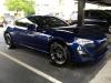
Pulled the car apart to start the UEL and snapped a shot of the EL. Flex bellows are in route for those of you wondering about them

JDLAutoDesign is offline  
The Following User Says Thank You to JDLAutoDesign For This Useful Post:
Tylub (01-25-2013)
Old 01-24-2013, 02:02 PM   #278
dabocx
Senior Member
 
dabocx's Avatar
 
Join Date: Jan 2012
Drives: Scion FRS
Location: United States
Posts: 1,267
Thanks: 564
Thanked 261 Times in 191 Posts
Mentioned: 9 Post(s)
One of the twin scroll BorgWarner EFR series turbos would be a blast on this car.
dabocx is offline  
Old 01-25-2013, 12:28 PM   #279
Jeff@Racer X Fab
Senior Member
 
Join Date: Aug 2012
Drives: Subaru BRZ, Toyota MR2 Turbo
Location: Lansing, MI
Posts: 321
Thanks: 92
Thanked 340 Times in 135 Posts
Mentioned: 23 Post(s)
...

Last edited by Jeff@Racer X Fab; 03-11-2013 at 08:36 AM.
Jeff@Racer X Fab is offline  
The Following User Says Thank You to Jeff@Racer X Fab For This Useful Post:
mikey_BRZ (01-25-2013)
Old 01-25-2013, 04:59 PM   #280
Lee@JDLAutoDesign
Member
 
Lee@JDLAutoDesign's Avatar
 
Join Date: Jan 2013
Drives: Corrado
Location: JDL
Posts: 32
Thanks: 4
Thanked 52 Times in 14 Posts
Mentioned: 1 Post(s)
Quote:
Originally Posted by racerx1715 View Post
Performing CFD with just the collector will give entirely different results than performing it with the entire manifold. In my opinion you would really need to study this analysis with the whole manifold to have a good idea of how effective the collector is. In addition you would need to run a dynamic flow simulation which would provide the actual data to get you in the ball park. From the manifold pictured above you would have flow seperation on the bends before entering the collector and this affects the data provided.
Sorry for the brief response but im typing on a cell phone from the rolex 24 @ daytona...

The runners upstream of the collector certainly can affect the pressure and velocity profiles entering the collector but the acceleration upstream of the throat is so strong that it really suppresses these effects. Ive actually done a study similar to what you describe and the impact on performance was very small... Certainly not enough to drive me to a different collector design.

Regarding the unsteady cfd... I dont have nearly enough computer resources to even attempt to simulate that (and in my personal experience most industrial cfd design work isnt even done unsteady).
Lee@JDLAutoDesign is offline  


Posting Rules
You may not post new threads
You may not post replies
You may not post attachments
You may not edit your posts

BB code is On
Smilies are On
[IMG] code is On
HTML code is Off

Forum Jump

Similar Threads
Thread Thread Starter Forum Replies Last Post
UEL Header Development 86drift Engine, Exhaust, Transmission 77 07-07-2016 01:45 AM
SRT Header Back Exhaust System Intro Piricing Swift Racing Technologies Engine, Exhaust, Bolt-Ons 51 09-25-2012 10:00 AM
Essex/AP Racing Competition Brake System in Development JRitt Brakes, Suspension, Chassis 1 06-14-2012 01:32 PM


All times are GMT -4. The time now is 08:05 PM.


Powered by vBulletin® Version 3.8.11
Copyright ©2000 - 2026, vBulletin Solutions Inc.
User Alert System provided by Advanced User Tagging v3.3.0 (Lite) - vBulletin Mods & Addons Copyright © 2026 DragonByte Technologies Ltd.

Garage vBulletin Plugins by Drive Thru Online, Inc.