


 09-21-2013, 09:22 PM
|
#379 | |
|
Senior Member
Join Date: Jun 2012
Drives: DGM BRZ limited
Location: Indiana
Posts: 366
Thanks: 98
Thanked 147 Times in 95 Posts
Mentioned: 8 Post(s)
Tagged: 0 Thread(s)
|
Quote:
I appreciate the transistor tech knowledge. I think at the moment none of us are trying to make our own brushless motor controller, its just added complexity I don't want to deal with when there are off the shelf options available.
__________________
 |
|

|

|
|
09-21-2013, 09:35 PM
|
#380 |
|
Senior Member
Join Date: Jun 2012
Drives: DGM BRZ limited
Location: Indiana
Posts: 366
Thanks: 98
Thanked 147 Times in 95 Posts
Mentioned: 8 Post(s)
Tagged: 0 Thread(s)
|
So Ive almost got my test setup ready to go. I decided that since I already have the prop spinners there wasn't a reason to go ahead and make a full standalone mount since I would probably need to do it again in the future anyways. For now these spinners will be able to hold the gears plenty fine, after all they are designed to hold props.
Ill just let the pics do the rest of the talking:     More info to come once I start them up.
__________________
|
|
|
|
| The Following 2 Users Say Thank You to rusty959 For This Useful Post: | DAEMANO (09-22-2013), neutron256 (09-21-2013) |
|
10-02-2013, 11:15 PM
|
#381 |
|
Junior Member
Join Date: Sep 2013
Drives: 91' Honda Civic; 91' 240sx;
Location: WI
Posts: 7
Thanks: 0
Thanked 5 Times in 5 Posts
Mentioned: 0 Post(s)
Tagged: 0 Thread(s)
|
EDF's Why they dont work, and how they could work. (Electric Ducted Fans)
Hi, I joined this forum just because of all the hype of Phantoms ESC has generated. This has gotten my creative juices flowing too and see if I could possibly do a DIY. I would like to share what I have gained from reading studies and other forums. Thomas Knight electrofied a roots and Phantom electrofied a centrifugal but I am going to focus only on Axial Compressors, like in jet engines.
WARNING: Wall of Text. First, I wanted to know, Why doesnt electric superchargers, the scam bilge blowers or ducted fan, not work? Then I wanted to know, How does a jet engine compressor section work and whats the difference? Heres what I found out. Contrary to popular belief, dynamic compressors, ie centrifugal and axial, DONT try to stuff big air into smaller volume like a positive displacement type like roots or screws. They generate high VELOCITY (air flow), then CONVERT that air flow into PRESSURE by slowing it down with the venturi effect (DIVERGENT duct). Fast flow = low pressure, low flow = high pressure, just like an airplane's wing. Each blade in an axial flow compressor are actually wings that create high and low pressure differences (pressure ratio) depending on blade pitch and number of stages, usually about 1.2 PR per stage in a typical jet engine. OK...so Why doesnt an EDF not create boost? Because it is only designed to create air flow, or velocity. There is nothing after the fan that converts that flow into pressure. The most any of these ducted fans can accomplish is to negate the vacuum created in the intake when your engine is in need of air, mostly at higher rpms. This DOES do something and its not entirely useless as it would be exactly like Phantom's drag reduction system, increasing throttle response, but not performance, and wasted electricity with no control. I would actually be interested in a cold air intake vs electric "supercharger/fan" test. I would actually put my bet that the electric fan would beat out the cold air intake, but thats just a guesstamate.  http://www.tppowerusa.com/edf-ducted.../tp-cnc-90-edf (this is a new EDF thats all CNC which I found to be the best candidate to convert to a compressor due to being all metal with the tightest tolerances, .5mm rotor to housing, and powerful motors) So next up, How does a jet engine (compressor stage) work and how does it convert that flow to pressure? The main difference is in the STATOR. Every STAGE of a jet has a ROTOR (fan) to acellerate the incoming air, and a STATOR, to slow that air down to create pressure. There are stators in EDF's, but they are more like air flow straighing vanes. An EDF would have to try and pressurize all volume of air from the fan to the valves to create pressure. In a jet, there are COUNTER ROTATING blades/wings in the stator instead of straight vanes, properly pitched to be balanced with the incoming velocity of the fan. Since the stators slow the air down to create pressure, to prevent stall, the air is pasted through smaller and smaller CONVERGENT DUCT. So, pressure in a jet compressor is created by the blades of the rotor and stator, and NOT stuffing more air in a smaller hole. Each stage in a typical jet compressor is good for about 1.2 PR, so for small boost applications, you would need a highly efficient single stage, or two stages. 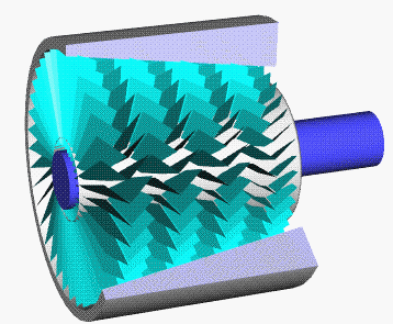  [ame="http://en.wikipedia.org/wiki/Axial_compressor"]Axial compressor - Wikipedia, the free encyclopedia[/ame] Now that we know how an actually axial flow compressor works, and why the regular EDF doesnt, how would we convert it into a compressor? A counter rotating stator ring/motor holder needs to be created to slow the velocity and create boost. So, the simplest way I could think of would be to CAD/Print a counter rotating stator ring to to slip over the motor inplace or behind the normal straight flow stator. Closest to the rotor (fan) would probably be most efficient. This would be considered a 1Motor/1Stage setup (or Vane Axial Fan for industrial fans). This would create more pressure than a standard EDF, but might not be enough for automotive use, as one stage doesnt produce a lot of pressure difference (PR), we would probably need two stages. Guess what...digging around, the RC aircraft scene has already modeled a 1Motor/2Stage "cold jet" compressor designed to run at 50k rpm Warhead 3545-1850kv motor. The motor could easily be swapped to a more powerful unit by designing a different mounting disk into the back of the compressor.  http://grabcad.com/library/two-stage...ric-ducted-fan (not sure if this is a ready to prototype design as its missing some screw threads but looks 95% complete. guy who designed this also use to work for General Electric turbos so im guessing he knows a thing or two about blade design) [ame="http://www.youtube.com/watch?v=-2WPx6uCIGY"]http://www.youtube.com/watch?v=-2WPx6uCIGY[/ame] (front on, you can see that there are no air gaps which is ideal for holding back pressure, but you can still see that air can pass at an angle even if the blades are stationary) Of course if we need more power, and/or more speed, I thought why not use two motors? Have one motor spinning the rotor as normal, and the other spinning the otherwise stationary stators (already counter rotating blades) in the opposite direction. So in a design like this, you would have two motors spinning two seperate rotors (no stators as the stator has now become a rotor) in opposite directions, in a push/pull manner (first rotor pushes air into second, counter rotating rotor). This I would consider a 2Motor/1Stage setup. What are benefits of this setup? Relative speed between the two rotors compared to the rotor/stator is twice as fast. In dynamic compressors, just like centrifugals, the faster you spin it, the more efficient it becomes and the more pressure difference you can create (given the same power). Another benefit is velocity drop is now negated due to the stator, which would normally slow the air, has now been turned into a rotor to increase velocity again. Now, since the second rotor now increases velocity back up, we could also now put a stator ring behind the second rotor to create a second compressor stage in a R/R/S config. First stage would be the high efficiency/high flow rotor to rotor stage, and second would be second rotor to stator like a normal stage. I call this a 2Motor/2Stage setup. This 2Motor/2Stage setup is getting pretty complicated compare to a regular 1Motor/1Stage, but we can get more complex. Instead of stationary stator rings, we can replace those with variable pitch guide vanes in the intake and exaust to direct and control flow into and out of the compressor. So the ultimate setup I have come up with is a 2Motor/2Stage w/vVanes to control BOTH flow and pressure. If this kind of compressor could be designed (I dont think its impossible) you could essentially get rid of the throttle body all together. For a 2Motor setup I would start with something like this:  http://rc-castle.com/shop/product_in...oducts_id=3339 flip one set of blades to be a pusher, and set it up inline nose to nose with blades closest to each other for max efficiency. You would end up with something like this 2Motor/1Stage: 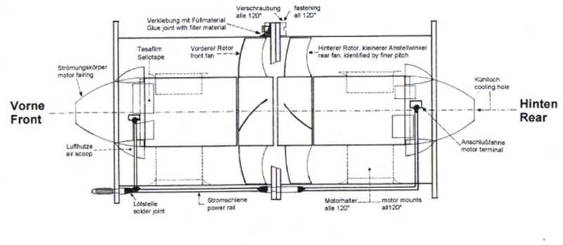 then ultimately this 2Motor/2Stages with Variable Guide Vanes:  All rings (Variable Vanes=green; Intake rotor=blue; Compression rotor=orange; Compression stator= yellow) modular for ease of install and custom ring configurations from 1Motor/1Stage up to 2Motor/2Stages. Well thats what I have gathered from reading various studies on counter rotating ducted fans and axial flow compressors. Dont throw out the ducted fan idea just because no one has made it work yet. Motor power and battery capacity (and super capacitors) have matured enough in the past few years that it is now possible to electrify a compressor (lower pressures and duty cycles) as Phantom has proven. ...I read both the this thread and the Phantom thread fully...it was tedious but informative. Last edited by Namwons; 10-03-2013 at 01:17 AM. |
|
|
|
| The Following User Says Thank You to Namwons For This Useful Post: | DAEMANO (10-03-2013) |
|
10-03-2013, 12:25 AM
|
#382 |
|
Junior Member
Join Date: Sep 2013
Drives: 91' Honda Civic; 91' 240sx;
Location: WI
Posts: 7
Thanks: 0
Thanked 5 Times in 5 Posts
Mentioned: 0 Post(s)
Tagged: 0 Thread(s)
|
Here is another RC jet engine that could be adapted to work. It uses an actual centrifugal compressor wheel with custom plates with divergent vanes. Just get rid of all the turbine stuff and add in the motor to drive the compressor side. This would be considered a mixed flow compressor, as the air comes in axially, gets thrown outward by the compressor wheel, then exits back out axially. Plans can be downloaded at the bottom here: http://members.tele2.nl/geraldensuzanne/turbines.htm
[ame="https://www.youtube.com/watch?feature=player_embedded&v=tJfH6ZVRKmk#t=66"]GR180 DIY Turbine in Solidworks - YouTube[/ame] Another idea I had was using an electric powered quasiturbine. If you dont know or never heard of a Quasiturbine, check it out here: http://quasiturbine.promci.qc.ca/ETypeCompressors.htm It can (theoretically, never tested) be used as an efficient internal combustion engine, as all four otto cycles are on the radial axis and one revolution produces 4 combustion stroke (continuous burn). In case of a compressor, every two lobes acts as a pump, so you would get two pumps when driven by an electric motor. As a compressor, it would be a positive displacement type. A quasiturbine could also be turned into a positive displacement turbocharger by connecting two lobes to the exhaust stream to drive it, and two lobes to intake and compress. Neat thing about the Quasi is its got a hollow center which you could put the electric motor in. So, in theory, create your own Hybrid electric turbocharger exhaust driven, electric assisted/generated. And you could also use a single quasi per cylinder, no need for twinscroll manifolds. 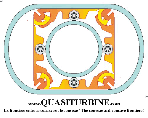
|
|
|
|
| The Following User Says Thank You to Namwons For This Useful Post: | DAEMANO (10-03-2013) |
|
10-03-2013, 12:43 AM
|
#383 |
|
Senior Member
Join Date: Jun 2012
Drives: DGM BRZ limited
Location: Indiana
Posts: 366
Thanks: 98
Thanked 147 Times in 95 Posts
Mentioned: 8 Post(s)
Tagged: 0 Thread(s)
|
I say go for it. Do some prototyping and see what you can come up with. Id say the worst thing is as you say you would need multiple stages to get a decent pressure ratio. But, you could get away with multiple smaller motors, which makes things a bit easier in some ways.
I don't completely understand how you would be planning on getting power to the fans further from the motor in your 4 fan/2 motor plan. Seems like the fan further from the other motor would be blocking it. But I haven't watched the videos yet, maybe it is answered in that.
__________________
|
|
|
|
|
10-03-2013, 12:53 AM
|
#384 |
|
Junior Member
Join Date: Sep 2013
Drives: 91' Honda Civic; 91' 240sx;
Location: WI
Posts: 7
Thanks: 0
Thanked 5 Times in 5 Posts
Mentioned: 0 Post(s)
Tagged: 0 Thread(s)
|
In the two motor plan, there is only two fans (blue fan and orange fan), one for each motor spinning in opposite directons with the motors nose to nose. The yellow/red is not a fan. Its a stator and is like a motor mount. The green are variable guide vanes to direct flow in and out, to pre-swirl the intake and straighten exhaust flow. The yellow and green would just be rings you slip on the back of the motor. Only things moving would be the two fan rotors. I will be trying this to see what it can push out. None of the stator or guide vane rings though, just two regular counter rotating EDF nose to nose (with one fan push other pull) in a 2Motor/1Stage setup to see what they can do before I decide on guide rings.
|
|
|
|
|
10-03-2013, 12:57 AM
|
#385 |
|
Senior Member
Join Date: Jun 2012
Drives: DGM BRZ limited
Location: Indiana
Posts: 366
Thanks: 98
Thanked 147 Times in 95 Posts
Mentioned: 8 Post(s)
Tagged: 0 Thread(s)
|
Got it, so then you would just have multiple of those setups?
__________________
|
|
|
|
|
10-03-2013, 01:01 AM
|
#386 |
|
Junior Member
Join Date: Sep 2013
Drives: 91' Honda Civic; 91' 240sx;
Location: WI
Posts: 7
Thanks: 0
Thanked 5 Times in 5 Posts
Mentioned: 0 Post(s)
Tagged: 0 Thread(s)
|
you would be able to add/remove guide rings as you see fit for custom stages or flow control, from a basic 1M/1S with no vanes up to 2M/2S with vanes.
|
|
|
|
|
10-03-2013, 10:36 AM
|
#387 |
|
Senior Member
Join Date: Jun 2012
Drives: DGM BRZ limited
Location: Indiana
Posts: 366
Thanks: 98
Thanked 147 Times in 95 Posts
Mentioned: 8 Post(s)
Tagged: 0 Thread(s)
|
Cool. So whats your current plan, Pick up that kit and see what type of performance you can get out of just two counter rotating fans? (I think thats a 2 stage setup?)
Also, what are you looking to put this on? I see you have a civic and 240sx. One of them?
__________________
|
|
|
|
|
10-03-2013, 12:50 PM
|
#388 |
|
Junior Member
Join Date: Sep 2013
Drives: 91' Honda Civic; 91' 240sx;
Location: WI
Posts: 7
Thanks: 0
Thanked 5 Times in 5 Posts
Mentioned: 0 Post(s)
Tagged: 0 Thread(s)
|
Yeah I will be trying just two regular counter rotating fans first to see what kind of presure they can build. It would just be a single stage with the two fans rotors. Second fan compresses air of the first. Two stages would need an additional stator compressor ring behind the second fan to compress the second fans air. Ill try this on my Civic first. Its just a daily driver gas saver (its stock 1.5, 35/38 mpg). With such low stock power, I should be able to tell the difference right away if it does anything. My 240 has got too much in it to be messing around with high current electricity lol. After that, if it does anything, ill try to design some stator rings and guide rings to increase pressure and control flow.
|
|
|
|
| The Following User Says Thank You to Namwons For This Useful Post: | neutron256 (10-03-2013) |
|
10-03-2013, 01:04 PM
|
#389 |
|
Senior Member
Join Date: Jun 2012
Drives: DGM BRZ limited
Location: Indiana
Posts: 366
Thanks: 98
Thanked 147 Times in 95 Posts
Mentioned: 8 Post(s)
Tagged: 0 Thread(s)
|
Exciting, I'm curious to see where this goes. I don't know what your technical background is, but if you need any assistance with control/electronics etc, let me know, I'd be happy to support a bit.
__________________
|
|
|
|
|
10-03-2013, 10:21 PM
|
#390 |
|
Member
Join Date: Sep 2013
Drives: GBS BRZ
Location: USA
Posts: 57
Thanks: 3
Thanked 18 Times in 13 Posts
Mentioned: 1 Post(s)
Tagged: 0 Thread(s)
|
I'm not sure there is any advantage to an axial compressor at this size. Garrett (and all other turbocharger manufacturers) use radial compressors because they can be easily made and require only one stage to get high pressure ratios. This makes them cheap and simple. For use in an electric supercharger, the radial compressors have the added advantage that someone else has already figured out how to extract 75, 76, even 77% efficiency. For an electric setup where input power is limited, efficiency is of paramount importance.
So what is the motivation to use an axial setup? |
|
|
|
|
10-03-2013, 11:37 PM
|
#391 |
|
Junior Member
Join Date: Sep 2013
Drives: 91' Honda Civic; 91' 240sx;
Location: WI
Posts: 7
Thanks: 0
Thanked 5 Times in 5 Posts
Mentioned: 0 Post(s)
Tagged: 0 Thread(s)
|
I just like to tinker with like everything. Why axial...because no one else is. Why follow in others foot steps? Im not trying to copy Phantom. Its all for science and the thirst for knowledge. And if it somehow succeeds, then I have a pretty cool stealth system. I wont know how good it is till I try and test for my self.
|
|
|
|
| The Following User Says Thank You to Namwons For This Useful Post: | neutron256 (10-04-2013) |
|
10-04-2013, 08:38 AM
|
#392 |
|
Senior Member
Join Date: Jun 2012
Drives: DGM BRZ limited
Location: Indiana
Posts: 366
Thanks: 98
Thanked 147 Times in 95 Posts
Mentioned: 8 Post(s)
Tagged: 0 Thread(s)
|
I'll also add that multiple motors of smaller size make power supply easier/cheaper. When you start running big motors drawing hundreds of amps the controllers get expensive and wires get larger and hard to deal with. If you can run with a few smaller motors the ESC's are cheap and you won't have to deal with gears and such like I am.
Pros and cons just like everything else.
__________________
|
|
|
|
|
|
|
|
| Tags |
| hairdyerperformance, only pulls hard one gear |
|
|
 Similar Threads
|
||||
| Thread | Thread Starter | Forum | Replies | Last Post |
| Full throttle Electric Supercharger Build Thread | fenton | Forced Induction | 11315 | 04-07-2025 06:42 PM |
| DUP THREAD MODZ PLZ DELETE KTHX | SloS14 | Forced Induction | 0 | 07-09-2013 05:41 PM |
| Electric Turbocharger | Shankenstein | Forced Induction | 91 | 06-24-2013 02:47 PM |
| Electric 86 | frosty86 | Scion FR-S / Toyota 86 GT86 General Forum | 8 | 11-10-2012 02:16 PM |
| WRX Electric turbo | Neilus | Engine, Exhaust, Transmission | 42 | 05-03-2012 09:20 PM |


