


 08-23-2013, 01:50 AM
|
#295 | |
|
Senior Member

Join Date: Jan 2012
Drives: '13 GBS Subaru BRZ
Location: Minneapolis, MN
Posts: 2,030
Thanks: 680
Thanked 664 Times in 382 Posts
Mentioned: 26 Post(s)
Tagged: 1 Thread(s)
|
Quote:
Edit: My dyslexia doesn't help either so I hope I said that right 
__________________
-Fortes fortuna adiuvat (Fortune favors the bold)
|
|

|

|
|
08-23-2013, 02:22 AM
|
#296 |
|
Senior Member
Join Date: Jan 2012
Drives: '13 GBS Subaru BRZ
Location: Minneapolis, MN
Posts: 2,030
Thanks: 680
Thanked 664 Times in 382 Posts
Mentioned: 26 Post(s)
Tagged: 1 Thread(s)
|
I've been reading more in the 'B2B Electric Supercharger' e-book tonight.
http://b2belectricsupercharger.com/ In their design which appears to be much of what the Phantom Supercharger is based on (or maybe the other way around) they are using a 12V setup. This made me think that maybe that's what I should be trying for in my first prototype. This would have one huge advantage in that the charging system becomes extremely simple. When I checked out 12V motors I was pretty impressed with what I found. SkyRC Toro SCT 4600Kv Max Power: 2000w Voltage limits: 18v; up to 4s lipo Max current: 180a Brushless KV: 4600 Resistance: .005ohm Shaft: 5mm x 15.5mm Dimensions(L*W): 62.5mm*36mm Weight:220g For a 12V nominal volatage that's 55K rpm. I'm sure actual speed it won't be that good, but that might work well with the smaller 20g compressor I currently have. Another advantage is that my original concept to use Ultracapacitors should work just fine at 12V. Ultra capacitors will charge/discharge much faster, and more efficiently then SLA batteries (about 95% vs 60% efficient).
__________________
-Fortes fortuna adiuvat (Fortune favors the bold)
|
|
|
|
| The Following User Says Thank You to neutron256 For This Useful Post: | DAEMANO (08-24-2013) |
|
08-23-2013, 02:27 AM
|
#297 | |
|
Senior Member
Join Date: Jun 2012
Drives: DGM BRZ limited
Location: Indiana
Posts: 366
Thanks: 98
Thanked 147 Times in 95 Posts
Mentioned: 8 Post(s)
Tagged: 0 Thread(s)
|
Quote:
Or, are you saying since you say this should be an isolated system, we will only be charging from 12v or powering the e-charger with 36v? If that is the case, one other possible benefit I was hoping to explore was the possibility of running the e-charger in some partial throttle conditions off of 12v, then have it automatically flip to 36v at a specified threshold. Which is why I had it set up to be either 12v or 36v. Obviously I'm not 100% this would work and would highly depend on the motor controller being used as well as how I programmed the controller, but I don't think it is out of the question. Now what I do know is the motor controllers usually don't turn on instantly, so you couldn't expect a system that only gets power when you want to make boost to be ready that instant. Where you are saying to throw this extra relay could obviously make a big difference, but would you mind citing reasons why it should be isolated? I don't disagree that in an optimum world it would be, but from this schematic, it doesn't absolutely have to be. And doesn't have to be means one fewer battery which means less cost and less weight. Could the batteries not have perfectly the same charge in this case? Yes, but for the short amount of time the e-charger is on, it wouldn't be a big deal. Nor is having a different charge really that big of a deal as long as you aren't depleting them too far, which is even less of a problem if you use deep cycle batteries as I am planning. edit: Is this what you were meaning?: 
__________________
 |
|
|
|
|
|
08-23-2013, 10:18 AM
|
#298 | |
|
Senior Member
Join Date: May 2013
Drives: FR-S 10 #103 AT
Location: NC
Posts: 1,519
Thanks: 101
Thanked 599 Times in 347 Posts
Mentioned: 5 Post(s)
Tagged: 0 Thread(s)
|
Quote:
Past experience with power supplies (long past, admittedly) makes me leery of making one battery be part of an active, constantly fluctuating system (the car) and also share duties with other batteries as part of a different system. It might very well not be as big a deal as I remember, but my memory just tells me it's wrong, even if I don't remember the exact reason. I want to see an isolator on this like they use for car stereos to keep one from affecting the other. Question: would deep cycle batteries have a rapid enough discharge rate compared to regular battery design to drive the electrocharger satisfactorily?
__________________
Necessity may be the mother of Invention but Desperation is quite often the father.
Sex is like Bridge. If you don't have a good partner, you'd better have a good hand. - Mae West Papa said, "son there's a lot of evil temptations out there. Best to try 'em all so you know which ones to avoid." |
|
|
|
|
|
08-23-2013, 11:34 AM
|
#299 | |
|
Senior Member
Join Date: Jan 2012
Drives: '13 GBS Subaru BRZ
Location: Minneapolis, MN
Posts: 2,030
Thanks: 680
Thanked 664 Times in 382 Posts
Mentioned: 26 Post(s)
Tagged: 1 Thread(s)
|
Quote:
A deep cycle battery might work fine depending on the size. If you're trying to stick with smaller batteries a standard SLA is probably going to be the best bet since you most likely won't be deep cycling (discharging most of the battery's capacity)
__________________
-Fortes fortuna adiuvat (Fortune favors the bold)
|
|
|
|
|
| The Following User Says Thank You to neutron256 For This Useful Post: | DAEMANO (08-24-2013) |
|
08-23-2013, 01:06 PM
|
#300 | |
|
Senior Member
Join Date: Jun 2012
Drives: DGM BRZ limited
Location: Indiana
Posts: 366
Thanks: 98
Thanked 147 Times in 95 Posts
Mentioned: 8 Post(s)
Tagged: 0 Thread(s)
|
Quote:
The good news is batteries like this are a lot more simple than power supplies. While throwing some power supplies in parallel and driving a big load can be risky as you know, these batteries are pretty dumb. When you throw them in parallel to charge, they all see the same charging voltage. In simple terms, if one is more discharged than another, its just going to draw a bit more current than the others and charge faster, or continue to charge after the others have finished. It doesn't really matter, because in theory none will ever be completely discharged so everything happens silently. So in essence, if you have one battery that is also doing main system duties while also being part of the 36v series system, if it happens to get slightly more discharged during the short time the 36v system is engaged, it shouldn't really be a big deal. It will just charge back up later. Who knows, it might even stay more charged part of the time since it will still be hooked up to the alternator while the 36v system is engaged, but of course this will depend on too many factors and it doesn't really matter. Also, in the real car audio world (which I also frequent) no one actually uses the battery isolators. Some shops might still try to make some extra money by telling customers they need it, but the ones who do it as a hobby never use them. As far as the deep cycle battery question, here is the battery I will likely use: http://4xspower.com/shop/d-series/d925/ In the past I used just one of these as the only battery in my 93 Ford Probe (v6) as a temp solution and it started just fine, so current won't be a problem. Now this battery is obviously a bit bigger than absolutely necessary, but as I said they will be doing double duty as powering my stereo.
__________________
|
|
|
|
|
| The Following User Says Thank You to rusty959 For This Useful Post: | DAEMANO (08-24-2013) |
|
08-23-2013, 11:43 PM
|
#301 |
|
Senior Member

Join Date: Sep 2012
Drives: stock
Location: ALBERTA CANADA
Posts: 117
Thanks: 31
Thanked 81 Times in 7 Posts
Mentioned: 1 Post(s)
Tagged: 0 Thread(s)
|
hey why so complicado?
Just throw a resistor in the fuel injector pulse to the esc input like they do with watermeth injectors Simple as lambda. KISS http://www.mrtrally.com.au/performance/docs/WRX-V5.pdf Last edited by PowderfaceTr.; 08-23-2013 at 11:48 PM. Reason: http://www.mrtrally.com.au/performance/docs/WRX-V5.pdf |
|
|
|
|
08-24-2013, 12:25 AM
|
#302 | |
|
Senior Member
Join Date: Jan 2012
Drives: '13 GBS Subaru BRZ
Location: Minneapolis, MN
Posts: 2,030
Thanks: 680
Thanked 664 Times in 382 Posts
Mentioned: 26 Post(s)
Tagged: 1 Thread(s)
|
Quote:
__________________
-Fortes fortuna adiuvat (Fortune favors the bold)
|
|
|
|
|
|
08-24-2013, 01:46 AM
|
#303 |
|
Senior Member
Join Date: Dec 2012
Drives: 2013 Scion FR-S
Location: Vancouver
Posts: 328
Thanks: 93
Thanked 113 Times in 65 Posts
Mentioned: 3 Post(s)
Tagged: 0 Thread(s)
|
o.o
|
|
|
|
|
08-24-2013, 11:50 AM
|
#304 | |
|
Senior Member
Join Date: Jun 2012
Drives: DGM BRZ limited
Location: Indiana
Posts: 366
Thanks: 98
Thanked 147 Times in 95 Posts
Mentioned: 8 Post(s)
Tagged: 0 Thread(s)
|
Quote:
__________________
|
|
|
|
|
|
08-24-2013, 12:35 PM
|
#305 | |
|
Senior Member
Join Date: Jan 2012
Drives: '13 GBS Subaru BRZ
Location: Minneapolis, MN
Posts: 2,030
Thanks: 680
Thanked 664 Times in 382 Posts
Mentioned: 26 Post(s)
Tagged: 1 Thread(s)
|
Quote:
With unichip you can create a boost MAP that normally would be used to control a turbo waste gate. It uses a simple duty cycle signal set at whatever frequency you want. You fill in the various load/RPM sites in the map with a duty cycle % value. This is then sent out on one of the Unichip outputs For those not familiar with RC brushless motors they use servo signals which are basically a duty cycle signal, but instead of % of the duty cycle they look at the High time in the signal. The high time should be from 1-2 ms/cycle. Assuming we set the signal for 100 Hz: 10% = 1ms = Full reverse 15% = 1.5ms = Center off 20% = 2ms = Full forward Doing this of course requires a Unichip tuners license which I got specifically for this, but if you have a local Unichp Tuner it should be pretty simple for them to set up. I can also share my maps with anyone interested and if they have the upload cable they can upload them themselves. Of course with the disclaimer that I'm not a tuner and make no promises to as to the safety of the tune. Unichip provides tuners with a great manual which is almost a complet how-to-guide on tuning. So if anyone has questions about Unichip I'll be happy to answer as best I can. Edit: I'm not an expert on servos so if anyone sees anything incorrect with my explanation please say so.
__________________
-Fortes fortuna adiuvat (Fortune favors the bold)
Last edited by neutron256; 08-24-2013 at 12:46 PM. |
|
|
|
|
| The Following User Says Thank You to neutron256 For This Useful Post: | DAEMANO (08-24-2013) |
|
08-24-2013, 04:33 PM
|
#306 | |
|
Senior Member
Join Date: Jun 2012
Drives: DGM BRZ limited
Location: Indiana
Posts: 366
Thanks: 98
Thanked 147 Times in 95 Posts
Mentioned: 8 Post(s)
Tagged: 0 Thread(s)
|
Quote:
From what I've seen, you will need to use 50hz for the servo control. Apparently some devices can technically run higher or lower, but 50hz is the standard. Also, the distinct pulse width that will correspond to reverse/center/forward will change a bit. Depending on your controller, you may not have a reverse, which is pretty typical with controllers intended for use with aircraft. Ground based units will usually have the ability to disable it. Regardless, you probably already know this, so this may just be for the benefit of those who don't, but the controllers usually need set up in regards to what is driving them. They will typically have you do something along the lines of center (or off if there is no reverse) so it can get the base, and then full on, and then reverse if there is one. This is just to take care of the minute differences between r/c controllers or whatever you are driving it with. I only mention this because it may or may not be difficult to do with the unichip if you are planning on running it strait off of it. If you are still going to have another device between the unichip and motor controller then I suppose it depends on that device. Either way faking the signal shouldn't be a problem if needed, just something to consider. My only reservation about running directly off the unichip is 1-2ms at 50hz is a pretty narrow range of duty cycle and I don't know the resolution you are able to use, although for this application you may not really need much resolution.
__________________
|
|
|
|
|
| The Following User Says Thank You to rusty959 For This Useful Post: | DAEMANO (08-31-2013) |
|
08-24-2013, 05:58 PM
|
#307 | |
|
Senior Member
Join Date: Jan 2012
Drives: '13 GBS Subaru BRZ
Location: Minneapolis, MN
Posts: 2,030
Thanks: 680
Thanked 664 Times in 382 Posts
Mentioned: 26 Post(s)
Tagged: 1 Thread(s)
|
Quote:
From my understanding 30-50 Hz is pretty standard for servos, most will work just fine up to 100 Hz and many will even work up to 250 Hz. I may have to experiment some to find out the limits of my controller. I plan to run mine at the highest frequency I can get to work consistently with the motor controller. I know unichip will allow at least one decimal place for duty cycle inputs maybe more. Load sites are also not absolute values for the output. If say the RPM is between two map sites (as will almost always be the case) it will varry the output accordingly. Example: 4000 RPM duty cycle = 15% 5000 RPM duty cycle = 17% At 4500 it would output 16% At 4750 it would output 16.5% I'm not sure how high the resolution is between map sites but I think it's very high. I need to get an oscilloscope so I can so I can troubleshoot is I have any problems. Here is a Unichip screenshot just to give you a feel for it. 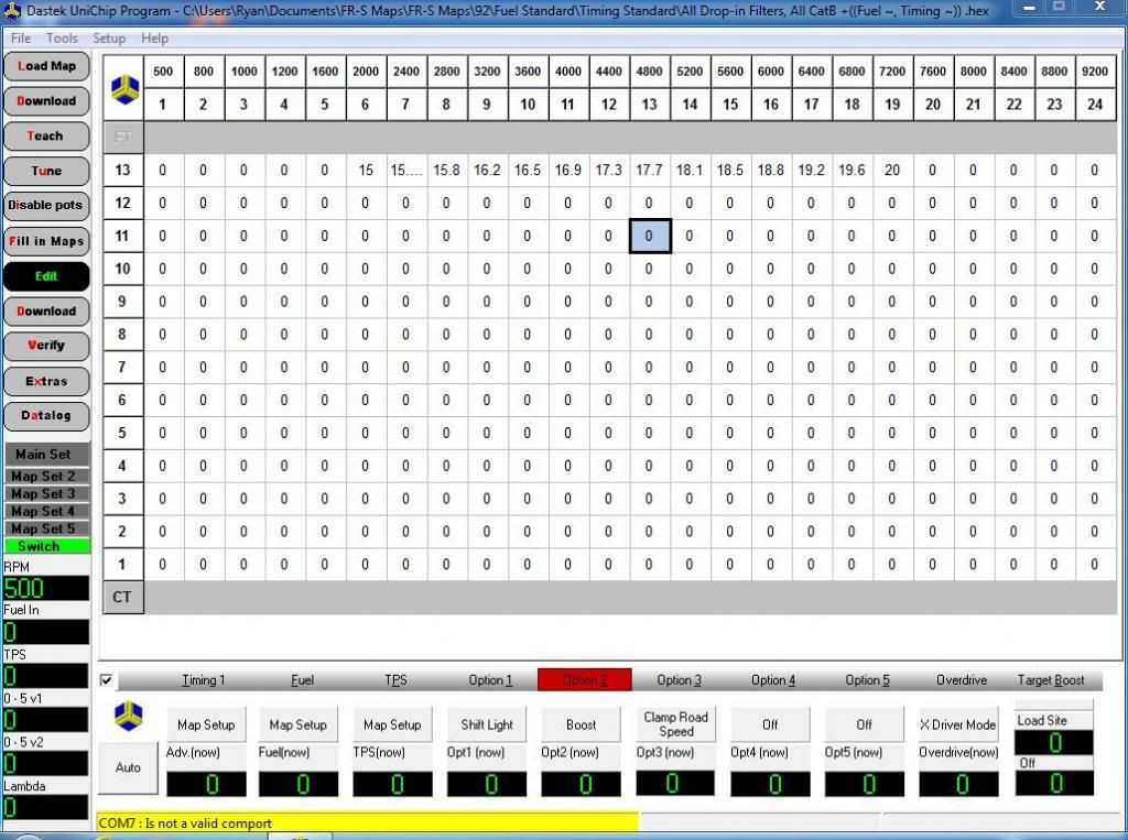
__________________
-Fortes fortuna adiuvat (Fortune favors the bold)
|
|
|
|
|
|
08-24-2013, 10:57 PM
|
#308 |
|
Senior Member

Join Date: Apr 2013
Drives: 2013 FR-S whiteout
Location: United States
Posts: 726
Thanks: 381
Thanked 652 Times in 256 Posts
Mentioned: 3 Post(s)
Tagged: 0 Thread(s)
|
Lookin good man!
|
|
|
|
|
|
|
|
| Tags |
| hairdyerperformance, only pulls hard one gear |
|
|
 Similar Threads
|
||||
| Thread | Thread Starter | Forum | Replies | Last Post |
| Full throttle Electric Supercharger Build Thread | fenton | Forced Induction | 11315 | 04-07-2025 07:42 PM |
| DUP THREAD MODZ PLZ DELETE KTHX | SloS14 | Forced Induction | 0 | 07-09-2013 06:41 PM |
| Electric Turbocharger | Shankenstein | Forced Induction | 91 | 06-24-2013 03:47 PM |
| Electric 86 | frosty86 | Scion FR-S / Toyota 86 GT86 General Forum | 8 | 11-10-2012 03:16 PM |
| WRX Electric turbo | Neilus | Engine, Exhaust, Transmission | 42 | 05-03-2012 10:20 PM |


