


|
||||||
| Cosmetic Modification (Interior/Exterior/Lighting) Discussions about cosmetic mods. |
 |
|
|
Thread Tools | Search this Thread |
 03-22-2020, 05:31 PM
|
#15 |
|
ProCrastinationConsultant

Join Date: Sep 2013
Drives: '14 Ranger, '18 Tacoma 4Dr LB
Location: chicago-ish
Posts: 11,330
Thanks: 35,240
Thanked 13,674 Times in 6,782 Posts
Mentioned: 98 Post(s)
Tagged: 0 Thread(s)
|
your diagram is correct. it's entirely possible that wire did go to the fuse box under the hood. it's just not somewhere i would take it under normal circumstances.
the reason for the relay at all is so that no part of the oem wiring is being used to carry the load of the added lights(this is more of an issue with halogen lights. if they are led units, it really doesn't matter). many times, people will try to add lights to existing fuses/wires, and it can cause all sorts of issues either blowing fuses, or worse, blowing out vehicle computers that relied on different signals. the aftermarket in general has adopted this method to avoid that issue-- by using the oem circuits to trigger a battery-connected relay. it avoids all of the pitfalls of inadequate oem wiring causing issues, as well as ensures that everything is installed and powered correctly.
__________________
"The time you enjoy wasting is not wasted time"
 |

|

|
| The Following User Says Thank You to soundman98 For This Useful Post: | AugyIA (03-23-2020) |
|
03-22-2020, 09:09 PM
|
#16 |
|
Persona Non Grata

Join Date: Nov 2015
Drives: '15 BRZ (WRB)
Location: On the Border
Posts: 1,882
Thanks: 2,016
Thanked 2,780 Times in 1,200 Posts
Mentioned: 10 Post(s)
Tagged: 1 Thread(s)
|
Given that the system is wired (in a sense) backward. I'm going to go way out on a limb and suggest the yellow wire might need to go to ground.
Fuse Tap +12v ---|--->---------------------------Red/yellow spliced together Positive (white) relay trigger wire ---- -<---Blue Switch Ground -----------------------------------<- --Black One, (either red or yellow) was intended to be spliced into a wire that's hot when the lights are on thereby lighting the fog light symbol on the switch but only when the lights are on. In my arrangement the fog light symbol lights when the key is on and the bar lights when the key is on and switch is closed. The other (Yellow or red) is the switched power to the relay. Closing the switch sends power down the blue wire to the positive trigger terminal on the relay. Let there be light. In addition it shunts a bit of current to light the little bar light on the switch. The black wire just grounds the switch so the lights in the switch work. OK. Looking at your diagram, you appear to have 12v coming from the battery directly to one of the trigger wires on the relay. Another wire runs from the other side of relay to the switch. When the switch is closed it completes the circuit and energizes the relay. Please don't take offense, but this looks bass ackward to me. So take everything else I say with some salt. One side of the switch still needs to be connected to 12v. That's what the red wires do. You also need to have a ground so the switch can complete the circuit. I don't think the switch ground (black wire) will do that. If all that is true, you need to ground it somehow to complete the circuit. It looks like the design intended to bring power into the switch through the red wire(s) and send it through the yellow wire. This circuit is not designed that way. Given the way yours is configured, the yellow most likely needs to go to ground. Done this way, I think it should work, but I don't thing the lights in the switch will do what they're intended to. I recommend getting a multi-tester and doing continuity checks across all the switch leads or pins in both the on and off positions of the switch. That will tell you which terminal is doing what. I expect that one of the reds will show no resistance with the yellow when the switch is closed. I'm a little leery of advising the next step because I can't tell what the rest of your wiring set up looks like, and don't want you to set your car on fire - but you could ... 2) connect the power wire to the battery. Install the switch and turn it off. Go to the yellow wire. Use the 12 or whatever setting on the multi-tester and see if you have power - you should not. Turn the switch to ON. I think the switch may light up. Go to the yellow wire. Use the 12 or whatever setting on the multi-tester and see if you have power. You should see 12v. If so, the yellow is the ground. @Soundman I suspect you are much better acquainted than I with this, so please amigo, does this make sense?
__________________
Slow is smooth, and smooth is fast
Last edited by Capt Spaulding; 03-22-2020 at 09:20 PM. |
|
|
|
| The Following User Says Thank You to Capt Spaulding For This Useful Post: | AugyIA (03-23-2020) |
|
03-23-2020, 12:20 AM
|
#17 |
|
ProCrastinationConsultant
Join Date: Sep 2013
Drives: '14 Ranger, '18 Tacoma 4Dr LB
Location: chicago-ish
Posts: 11,330
Thanks: 35,240
Thanked 13,674 Times in 6,782 Posts
Mentioned: 98 Post(s)
Tagged: 0 Thread(s)
|
@Capt Spaulding , he's missing a few things in the diagram, but it does make sense as it is knowing that.
[random relay pinout image] 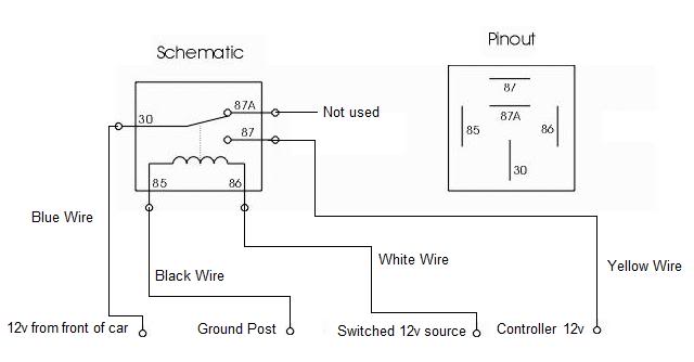 the red should only feed the output of the relay, so it would be on pin 87. the blue wires going to the fog lights should be connected at pin 30. note: pin 87 and 30 are reversible, depending on personal electrical theories the red wire from the switch will be on pin 86 the black at the relay should be directly connected to ground, and should be on pin 85. the 2 blacks from the lights would also be connected to ground. they likely connect together and then connect to the same ground point near the relay. note: pins 85 and 86 are also reversible. this diagram shows the exact reverse connection of the previous diagram.  85/86 are always the coil. one will get power from the triggering device, in this case, the switch, and the other will go directly to ground. it's highly recommended not to trigger things opposite by switching the ground, as any shorted connection, or damage to the switching wire will complete the circuit.
__________________
"The time you enjoy wasting is not wasted time"
|
|
|
|
| The Following User Says Thank You to soundman98 For This Useful Post: | AugyIA (03-23-2020) |
|
03-23-2020, 05:04 PM
|
#18 |
|
Member
Join Date: Mar 2020
Drives: 2014 Scion FR-S
Location: Iowa
Posts: 33
Thanks: 22
Thanked 7 Times in 6 Posts
Mentioned: 0 Post(s)
Tagged: 0 Thread(s)
|
Thank you both for all the information. I see I omitted one ground wire from my drawing and you were correct, the blacks from the fog light at the relay connection have a 3rd black wire that is grounded to the chassis at the relay.
Having read through all of both of your posts, I'm convinced you are right. That said, you both seem to suggest this isn't the correct or best way to wire the fog lights. I don't want to have issues, even if I could get it to work and I certainly don't need to catch the car on fire :-) There are inexpensive wiring harnesses available online, I think to be safe I will just replace the wiring with something that is "standard". I'll post back with results once I get something in and installed. I'll probably have more questions :-) Hopefully not! Thank you both, it's been very enlightening and I greatly appreciate you taking the time to try and sort this out. |
|
|
|
|
03-23-2020, 05:07 PM
|
#19 |
|
Member
Join Date: Mar 2020
Drives: 2014 Scion FR-S
Location: Iowa
Posts: 33
Thanks: 22
Thanked 7 Times in 6 Posts
Mentioned: 0 Post(s)
Tagged: 0 Thread(s)
|
This is the one I'm thinking would work... https://www.ebay.com/itm/H11-Fog-Lig...a/323268508435
It doesn't specify FR-S but it looks to be appropriate. Not sure the switch will fit but I could probably use my current switch. This might be another option... https://www.amazon.com/HUIQIAODS-Har...5001769&sr=8-5 Last edited by AugyIA; 03-23-2020 at 06:18 PM. |
|
|
|
|
03-23-2020, 06:34 PM
|
#20 |
|
Persona Non Grata
Join Date: Nov 2015
Drives: '15 BRZ (WRB)
Location: On the Border
Posts: 1,882
Thanks: 2,016
Thanked 2,780 Times in 1,200 Posts
Mentioned: 10 Post(s)
Tagged: 1 Thread(s)
|
The two sets look the identical to my eye. If I'd known a prefab was available, I wouldn't have spent $50+ building my own.
It still doesn't seem clear, given their circuit diagram, what happens at the switch? It should have power coming to it both for triggering the relay and lighting the leds in the switch itself.
__________________
Slow is smooth, and smooth is fast
|
|
|
|
| The Following User Says Thank You to Capt Spaulding For This Useful Post: | AugyIA (03-23-2020) |
|
03-23-2020, 07:31 PM
|
#21 | |
|
Member
Join Date: Mar 2020
Drives: 2014 Scion FR-S
Location: Iowa
Posts: 33
Thanks: 22
Thanked 7 Times in 6 Posts
Mentioned: 0 Post(s)
Tagged: 0 Thread(s)
|
Quote:
|
|
|
|
|
|
03-23-2020, 10:47 PM
|
#22 |
|
ProCrastinationConsultant
Join Date: Sep 2013
Drives: '14 Ranger, '18 Tacoma 4Dr LB
Location: chicago-ish
Posts: 11,330
Thanks: 35,240
Thanked 13,674 Times in 6,782 Posts
Mentioned: 98 Post(s)
Tagged: 0 Thread(s)
|
they look the same to me as well.
i see now that the relay's are not typical automotive relay's, so a lot of what i said isn't completely applicable.
__________________
"The time you enjoy wasting is not wasted time"
|
|
|
|
| The Following User Says Thank You to soundman98 For This Useful Post: | AugyIA (03-24-2020) |
|
03-24-2020, 01:20 PM
|
#23 | |
|
Member
Join Date: Mar 2020
Drives: 2014 Scion FR-S
Location: Iowa
Posts: 33
Thanks: 22
Thanked 7 Times in 6 Posts
Mentioned: 0 Post(s)
Tagged: 0 Thread(s)
|
Quote:
|
|
|
|
|
|
03-24-2020, 01:28 PM
|
#24 |
|
Persona Non Grata
Join Date: Nov 2015
Drives: '15 BRZ (WRB)
Location: On the Border
Posts: 1,882
Thanks: 2,016
Thanked 2,780 Times in 1,200 Posts
Mentioned: 10 Post(s)
Tagged: 1 Thread(s)
|
Augy, If you decide you want to build one, let me know. I have some extra materials from my project you are welcome to.
__________________
Slow is smooth, and smooth is fast
|
|
|
|
| The Following User Says Thank You to Capt Spaulding For This Useful Post: | AugyIA (03-24-2020) |
|
03-24-2020, 03:03 PM
|
#25 | |
|
Member
Join Date: Mar 2020
Drives: 2014 Scion FR-S
Location: Iowa
Posts: 33
Thanks: 22
Thanked 7 Times in 6 Posts
Mentioned: 0 Post(s)
Tagged: 0 Thread(s)
|
Quote:
|
|
|
|
|
|
03-27-2020, 08:53 AM
|
#26 |
|
Member
Join Date: Mar 2020
Drives: 2014 Scion FR-S
Location: Iowa
Posts: 33
Thanks: 22
Thanked 7 Times in 6 Posts
Mentioned: 0 Post(s)
Tagged: 0 Thread(s)
|
I installed one of the pre-made wiring harness I linked above. Not surprisingly, the simple wiring doesn't incorporate any switched power source. So, the backlight on the switch is on all the time. Also, this wiring method would allow the fog lights to run the battery down if left on.
The new harness is very similar to the old one without the modifications. I believe it was probably identical prior to the mods. The harness only has a black (-) and red (+) lead with ring terminals that have to be connected (beside the two H11 plugs and the block plug that connects to the switch. The "instructions" say to connect the two ring terminal leads directly to the battery. That works but, like I mentioned, it leaves the opportunity to run the battery down should you leave the lights on...and, the backlight on the switch is on always. There is a switched power source in the engine bay fuse box (unused). I came across that in some research. Image below. I'm considering running the red (+) lead from the relay harness to that point rather than directly to the battery. Do you think that is a safe way to address this or should I look at re-wiring the switch? Any input would be much appreciated. My main concern with running the positive lead to the fuse is whether it would be safe to do so. Thanks! 
|
|
|
|
|
03-27-2020, 09:11 PM
|
#27 |
|
ProCrastinationConsultant
Join Date: Sep 2013
Drives: '14 Ranger, '18 Tacoma 4Dr LB
Location: chicago-ish
Posts: 11,330
Thanks: 35,240
Thanked 13,674 Times in 6,782 Posts
Mentioned: 98 Post(s)
Tagged: 0 Thread(s)
|
it should really be fine. fog lights don't draw that much power
__________________
"The time you enjoy wasting is not wasted time"
|
|
|
|
| The Following User Says Thank You to soundman98 For This Useful Post: | AugyIA (03-28-2020) |
|
03-28-2020, 06:30 AM
|
#28 |
|
Member
Join Date: Mar 2020
Drives: 2014 Scion FR-S
Location: Iowa
Posts: 33
Thanks: 22
Thanked 7 Times in 6 Posts
Mentioned: 0 Post(s)
Tagged: 0 Thread(s)
|
Thanks for the reply, I was thinking that but wanted a second opinion.
|
|
|
|
|
|
|
|
|
|
|
 Similar Threads
|
||||
| Thread | Thread Starter | Forum | Replies | Last Post |
| GCS 4th brake light wiring question | msaikhan | Cosmetic Modification (Interior/Exterior/Lighting) | 0 | 06-20-2019 08:13 PM |
| DIY: Valenti 4th brake light wiring for no blink brake light. (Triangle) | BirdTRD | DIY (Do-It-Yourself) Guides | 17 | 11-06-2017 08:42 PM |
| Tail light wiring question | andrew_l_s | Cosmetic Modification (Interior/Exterior/Lighting) | 0 | 08-14-2015 10:13 PM |
| Valenti Rear fog light Wiring Question | xcooperx | Cosmetic Modification (Interior/Exterior/Lighting) | 2 | 08-03-2015 03:03 AM |
| Valenti rear bumper light wiring question... | Ridgerunr | Cosmetic Modification (Interior/Exterior/Lighting) | 2 | 04-25-2015 05:01 PM |


