


|
||||||
| DIY (Do-It-Yourself) Guides For all DIYs. |
 |
|
|
Thread Tools | Search this Thread |
 01-24-2015, 05:15 PM
|
#1 |
|
ProCrastinationConsultant

Join Date: Sep 2013
Drives: '14 Ranger, '18 Tacoma 4Dr LB
Location: chicago-ish
Posts: 11,330
Thanks: 35,240
Thanked 13,673 Times in 6,781 Posts
Mentioned: 98 Post(s)
Tagged: 0 Thread(s)
|
How To: BRZ infinite 1-5 headlamp adjustment(no more notches!)
my biggest problem with the car since getting it has always been that the interior headlamp adjuster steps are too large to be of any use.. put a couple things in the trunk, and i need 0.5 of a step more, not a whole step..
so today, i finally managed to fix that. the notchy-ness is from a ball bearing that is spring loaded in the back of the knob. the actual circuit board within the adjuster does allow for infinite 1-5 adjustment, so all that needs to be done is to remove the ball bearing and it's pressure spring from the back of the knob. tools needed:
parts needed:
start off by pulling the adjuster from the dash-- this seems to be most easily done by removing the small side panel next to the steering wheel, undo the philips-head screw located behind it, and pop the lower panel off to access the rear of the adjuster. the adjuster is held in with 2 small locking tabs, one on the top and one on the bottom. just insert the precision screwdrivers in between the insert and the adjuster housing and put some pressure on the screwdrivers and the front of the adjuster-- it should pop out pretty easily. it doesn't take much force.. after that, you just need to pop the adjuster apart. i used one of those precision screwdrivers to release 2 of the 4 tabs around the edge of the adjuster.. after that, you're in. the circuit board and the black connector both come out at the same time with a little bit of force on the other side of the connector. at this point, you'll be left with a spinning knob attached to the other side of the housing. the knob is held onto the housing with an aluminum shaft and a steel lock washer. you need to grind the aluminum down until the steel lock washer falls off. be very careful, and check the temperature of the back of the shaft often-- it's easy to heat up and could deform the housing. after that, it should all fall apart, and you'll be left with this 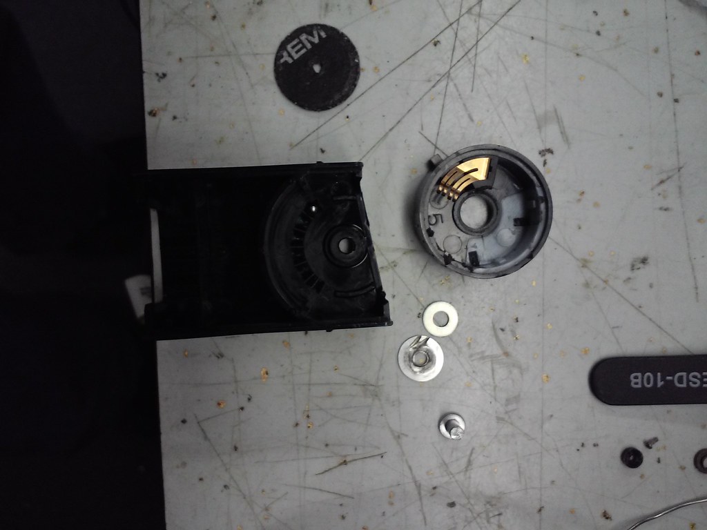 you can just barely make out the ball bearing in the notches in the housing. pull the ball bearing and it's spring out of the way, and re-assemble! using the 10mm M3 screw and it's locknut, reassembling should look like this-- the 10mm screw will be just a couple threads too long, and will push the led up, preventing the rear of the housing from snapping on. 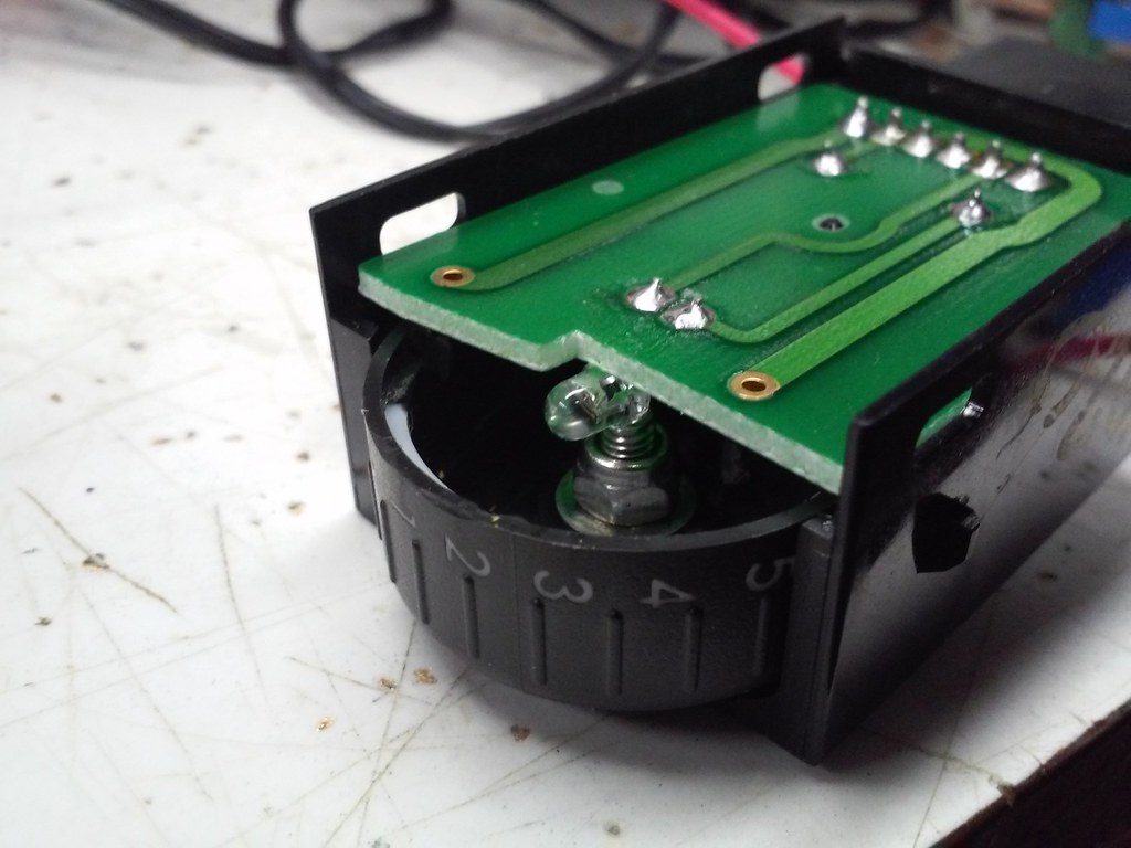 i pulled the circuit board out of the way and marked it with a marker to make sure i didn't grind too much off 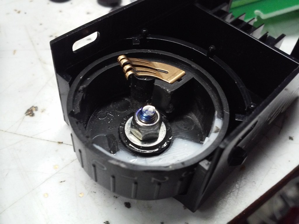 and presto. the led clears the screw, the circuit board fits how it's supposed to, time to snap the back cover back on. after that, it's just a matter of re-installing in the car-- everything snaps together, so i don't believe it's all that difficult.. test that everything still works, and now you should be able to adjust your headlights however you want from within the car!!
__________________
"The time you enjoy wasting is not wasted time"
 |

|

|
|
01-24-2015, 11:20 PM
|
#2 |
|
There are now 2 carseats!
Join Date: Nov 2012
Drives: 2013 DGM BRZ
Location: The Emerald City
Posts: 434
Thanks: 21
Thanked 166 Times in 75 Posts
Mentioned: 7 Post(s)
Tagged: 0 Thread(s)
|
Can you link to how to properly aim headlights. I feel like a lot of members could benefit from that, myself included. I forgot how and what is proper.
|
|
|
|
|
01-24-2015, 11:42 PM
|
#3 |
|
ProCrastinationConsultant
Join Date: Sep 2013
Drives: '14 Ranger, '18 Tacoma 4Dr LB
Location: chicago-ish
Posts: 11,330
Thanks: 35,240
Thanked 13,673 Times in 6,781 Posts
Mentioned: 98 Post(s)
Tagged: 0 Thread(s)
|
i don't know if there is a proper link anywhere.. i believe the nhtsa/dot official standard is that the beam should drop about 1-2" for every 25' or so.. the problem is these cars are so low, i seem to end up aiming my headlights more so they are even with the ground overall--following the standard, it seems the beam hits the ground at 100' and i start over-driving the lights more...
overall, i make sure that it stays off the road signs, and stays well below most people's eyes the majority of the time..
__________________
"The time you enjoy wasting is not wasted time"
|
|
|
|
|
01-25-2015, 12:39 AM
|
#4 |
|
Senior Member

Join Date: May 2014
Drives: 2014 Pearl BRZ Limited
Location: Central Indiana
Posts: 263
Thanks: 105
Thanked 109 Times in 57 Posts
Mentioned: 1 Post(s)
Tagged: 0 Thread(s)
|
Great write-up THANKS! Definitely plan on doing this..
__________________
 | OFT & Stg2 e85 Tune | Perrin Intake Tube & High Flow Filter | Perrin Lightweight Crank Pully | | Tomei UEL Header/Overpipe | HFC/Perrin Catback | Tom's Tails | Enkei RPF1's | RS*R SuperDowns | |
|
|
|
|
01-25-2015, 09:57 AM
|
#5 |
|
Senior Member
Join Date: Mar 2013
Drives: 2019 Mazda Miata RF
Location: Earth
Posts: 2,105
Thanks: 979
Thanked 1,317 Times in 736 Posts
Mentioned: 23 Post(s)
Tagged: 1 Thread(s)
|
The ball detent should also keep the switch from rotating on it's own. Have you noticed the headlights adjusting themselves due to road vibration at all?
|
|
|
|
|
01-25-2015, 03:28 PM
|
#6 |
|
Senior Member
Join Date: Mar 2013
Drives: 2013 FR-S
Location: Omaha, NE
Posts: 307
Thanks: 84
Thanked 128 Times in 68 Posts
Mentioned: 2 Post(s)
Tagged: 0 Thread(s)
|
I'm not an electrical engineer, but looking at what I see there, I don't think that you can have "infinite" adjustment. You would need something like a potentiometer type switch in there with variable voltage/resistance for that to work how you planned it. The system that is in place looks like it just changes the electrical contacts based on one of the predetermined notched positions.

|
|
|
|
|
01-25-2015, 04:30 PM
|
#7 |
|
Senior Member
Join Date: Oct 2013
Drives: 2015 Series.Blue
Location: Fort Worth, TX
Posts: 1,781
Thanks: 88
Thanked 781 Times in 481 Posts
Mentioned: 16 Post(s)
Tagged: 0 Thread(s)
|
OP left out pictures of the circuit board... it could allow near infinite adjustment but I'd have to see it to know. I'm not taking mine apart to do it though...
|
|
|
|
|
01-27-2015, 11:10 PM
|
#8 | |||
|
ProCrastinationConsultant
Join Date: Sep 2013
Drives: '14 Ranger, '18 Tacoma 4Dr LB
Location: chicago-ish
Posts: 11,330
Thanks: 35,240
Thanked 13,673 Times in 6,781 Posts
Mentioned: 98 Post(s)
Tagged: 0 Thread(s)
|
Quote:
Quote:
 rule #1 of electronics modding -- NEVER mod your only housing unless you know 100% what you're doing! here's pics of my original unit opened up.. the one i put in the car and first modded in this tutorial was off ebay-- but the mod was so simple turns out i didn't really need to do that anyways.. good/bad habit from my last car where i had to tweak and tune everything as i went to get it all to work.. so i always get a replacement 'whatever' that i mod, and keep the original for later when i want to revert back.. 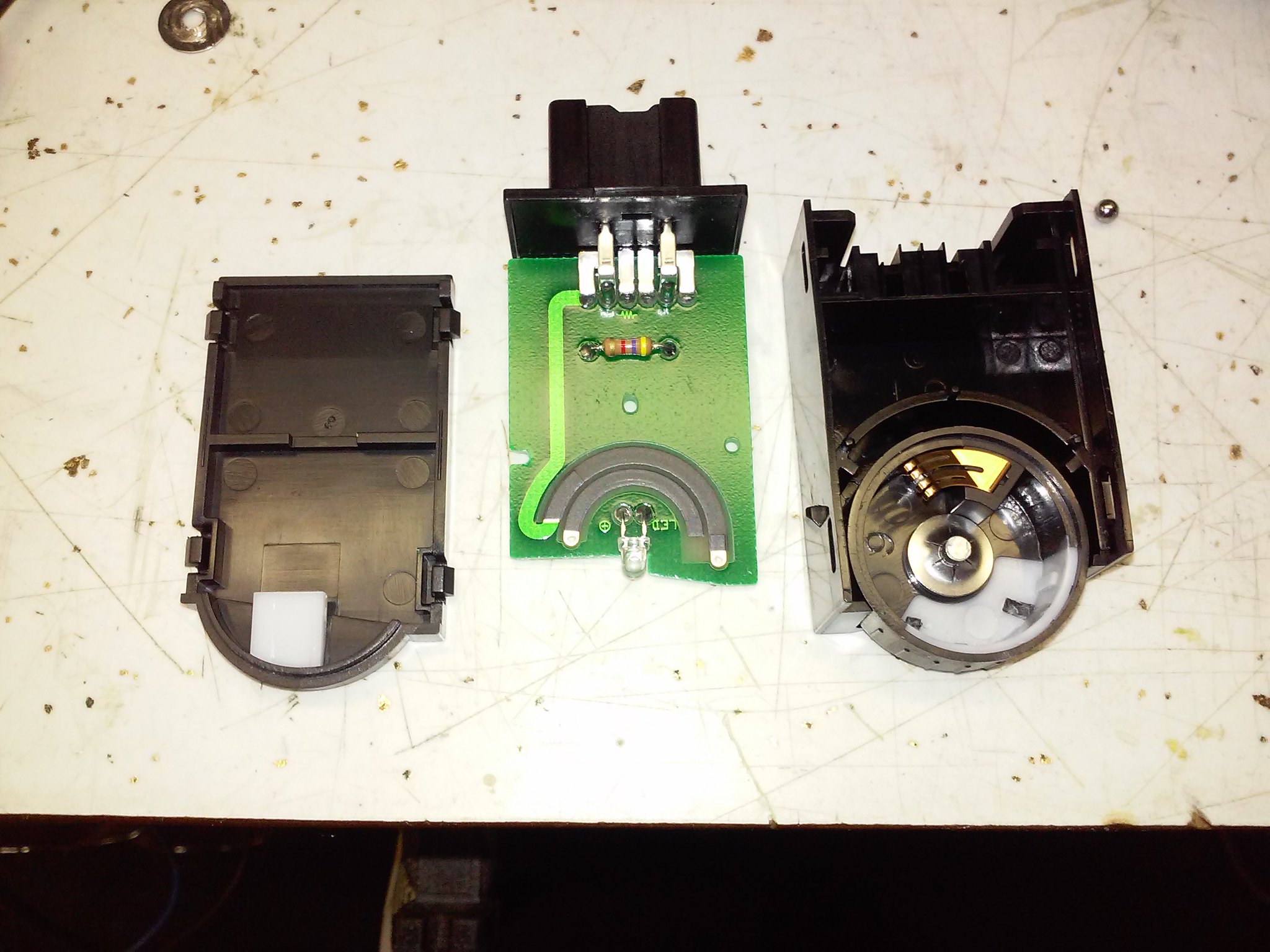 the control uses the same resistance material that the touch pads of any momentary soft-touch button has-- like in a calculator.. shorting between the material at different spots changes the resistance it outputs. the fact that they use this design makes this tutorial usable. and fyi-- i also opened up the dimmer as well, and that is what this looks like. this design can't be modified to work any better-- it has the notches you suspected were in the headlamp height adjuster 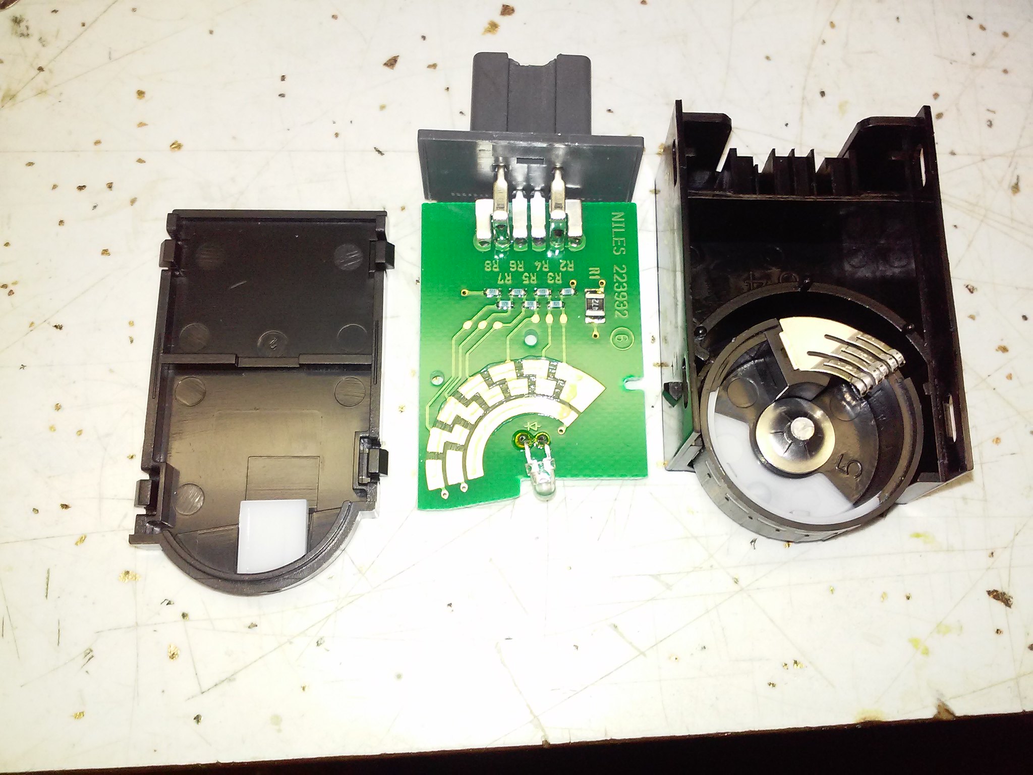 i was dissapointed, as having infinite adjustment on that as well would be really cool, but not really needed for me.. Quote:
i wouldn't have taken the time to write the tutorial unless it works... that's part of the reason i'm lacking on the pictures-- i did it all myself on my own car, verified it worked, and then did the write-up.. everyone's scared to mod their cars outside of parts they can buy off ebay... stay tuned for my next thread-- i'm building a 13k+ lumen reverse light-- that will fit within the oem reverse light housing...
__________________
"The time you enjoy wasting is not wasted time"
|
|||
|
|
|
| The Following User Says Thank You to soundman98 For This Useful Post: | bfsnail (01-28-2015) |
|
|
|
|
|
|
|
 Similar Threads
|
||||
| Thread | Thread Starter | Forum | Replies | Last Post |
| FR-S driver side headlamp | ultra_frs | Exterior Parts (Aero, Lighting, Etc.) | 4 | 08-18-2013 04:57 PM |
| BRZ Right Headlamp Assembly Available | pd | Exterior Parts (Aero, Lighting, Etc.) | 0 | 04-26-2013 06:16 PM |
| Headlamp Mods - Diminished Light | FRSFirestorm | Cosmetic Modification (Interior/Exterior/Lighting) | 4 | 01-03-2013 01:27 PM |
| A Cool Article / FR-S Body Kit / Infinite-Garage.com | KronosPerformance | Cosmetic Modification (Interior/Exterior/Lighting) | 3 | 07-12-2012 07:57 AM |


 SWP
SWP BLT4CRVS
