


|
||||||
| Engine, Exhaust, Transmission Discuss the FR-S | 86 | BRZ engine, exhaust and drivetrain. |
 |
|
|
Thread Tools | Search this Thread |
 11-22-2018, 06:52 PM
|
#15 | |
|
義理チョコ

Join Date: Sep 2014
Drives: a 13 e8h frs
Location: vantucky, wa
Posts: 31,865
Thanks: 52,120
Thanked 36,513 Times in 18,917 Posts
Mentioned: 1106 Post(s)
Tagged: 9 Thread(s)
|
Quote:

__________________
Last edited by Ultramaroon; 11-23-2018 at 12:56 AM. Reason: better image |
|

|

|
| The Following User Says Thank You to Ultramaroon For This Useful Post: | Calum (12-01-2018) |
|
11-24-2018, 01:07 AM
|
#16 | |
|
義理チョコ
Join Date: Sep 2014
Drives: a 13 e8h frs
Location: vantucky, wa
Posts: 31,865
Thanks: 52,120
Thanked 36,513 Times in 18,917 Posts
Mentioned: 1106 Post(s)
Tagged: 9 Thread(s)
|
Quote:
__________________
|
|
|
|
|
| The Following User Says Thank You to Ultramaroon For This Useful Post: | Calum (12-01-2018) |
|
11-24-2018, 07:49 AM
|
#17 |
|
Senior Member

Join Date: Sep 2017
Drives: 2022 BRZ Limited Silver
Location: Jacksonville, FL
Posts: 2,532
Thanks: 882
Thanked 2,045 Times in 1,188 Posts
Mentioned: 68 Post(s)
Tagged: 0 Thread(s)
|
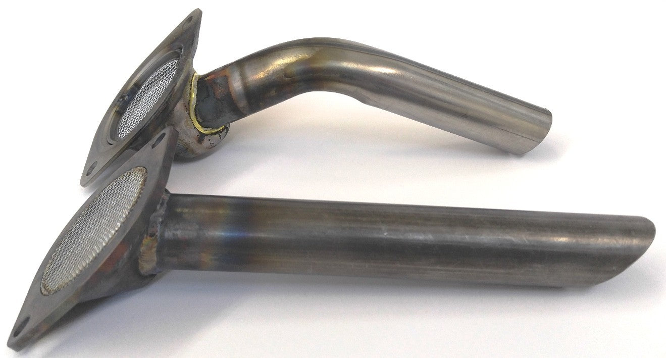
Here is a good comparison of OEM vs the Killer B.
 I spun my number 3 and studied the oiling for weeks but wasnt comfortable trying to do anything dramatic about it. Number 2 and 3 sharing one feed on the crank seemed like a bad design to me. The only thing I did on mine was smooth out all the casting imperfections in the pump on the timing cover. Mine was a mess. Relocating the thermometer seems like an easy mod too. I also found it odd how one head seems to get more priority. The holes in the rocker pivots are not the same between bank 1 and 2 either. This changed in 2014 though. They now use the same pivots on both banks and they are more restrictive then either bank on the old design. Not sure if this was to bias more flow to the bottom end or create more lift for the rocker or both. Im wishing I got the Killer B when I did my rebuild. Couldnt hurt. |
|
|
|
| The Following 3 Users Say Thank You to ermax For This Useful Post: |
|
11-24-2018, 11:34 AM
|
#18 | |
|
Senior Member
Join Date: Sep 2017
Drives: 2022 BRZ Limited Silver
Location: Jacksonville, FL
Posts: 2,532
Thanks: 882
Thanked 2,045 Times in 1,188 Posts
Mentioned: 68 Post(s)
Tagged: 0 Thread(s)
|
Quote:
I saw a photo of the crank where the main feed for 2 and 3 looked bigger but my crank sure as hell didnt look bigger. It makes no since for it not to be a tad bigger. It was tempting to drill it but I figured there must be some reason they did it this way that isnt obvious to me. |
|
|
|
|
| The Following 2 Users Say Thank You to ermax For This Useful Post: | Calum (12-01-2018), Ultramaroon (11-24-2018) |
|
11-24-2018, 01:59 PM
|
#19 |
|
Member
Join Date: Sep 2018
Drives: Car
Location: Earth
Posts: 50
Thanks: 7
Thanked 12 Times in 10 Posts
Mentioned: 0 Post(s)
Tagged: 0 Thread(s)
|
On the topic of oil stuff, I just tried a mod to my sandwich plate that helped out. I had a pressure drop after my oil cooler install. The manufacturer assured me the loss was normal and they have way more experience than me. Anyways, I drilled a hole through the sandwich plate. I started small and kept increasing the size of the hole until my redline oil pressure was close to where it was prior to the oil cooler install. I don't know a thing about thermodynamical stuff but the idea was that at all rpm's, some oil could bypass the cooler to increase flow but not enough to reduce cooling significantly. Max temps are 10° hotter but I gained 8psi even with the slightly higher temperatures. I started with a 3/16 hole and ended up with 5/16. Oil lines are an10.
|
|
|
|
| The Following 3 Users Say Thank You to remhex For This Useful Post: |
|
11-24-2018, 02:21 PM
|
#20 | |
|
義理チョコ
Join Date: Sep 2014
Drives: a 13 e8h frs
Location: vantucky, wa
Posts: 31,865
Thanks: 52,120
Thanked 36,513 Times in 18,917 Posts
Mentioned: 1106 Post(s)
Tagged: 9 Thread(s)
|
Quote:
Others may know but, to me it feels like Fuji is just now learning how to build a higher speed engine. It's pretty interesting to see them working around the err of their ways. I'm excited for your changes. Thanks for digging up those pics. Edit: Interesting that the cavity in the pump gears is still increasing in that arc segment where the supply cavity rapidly decreases on both sides. What purpose does that serve? Could the answer be as simple as opening up the channel to allow the pump to breathe more? Or would that introduce some sort of instability? 
__________________
Last edited by Ultramaroon; 11-24-2018 at 03:51 PM. |
|
|
|
|
| The Following User Says Thank You to Ultramaroon For This Useful Post: | Calum (12-01-2018) |
|
11-24-2018, 08:42 PM
|
#21 |
|
Senior Member
Join Date: Sep 2015
Drives: 2016 Halo FRS
Location: US
Posts: 414
Thanks: 290
Thanked 161 Times in 106 Posts
Mentioned: 8 Post(s)
Tagged: 0 Thread(s)
|
This has been the most educational thread in quite some time on this forum.
|
|
|
|
| The Following 3 Users Say Thank You to Trust86 For This Useful Post: |
|
11-24-2018, 09:31 PM
|
#22 | |
|
義理チョコ
Join Date: Sep 2014
Drives: a 13 e8h frs
Location: vantucky, wa
Posts: 31,865
Thanks: 52,120
Thanked 36,513 Times in 18,917 Posts
Mentioned: 1106 Post(s)
Tagged: 9 Thread(s)
|
Quote:
Do you agree that the restriction is further upstream? That over-driven, the whole cavity between the critical restriction and the pump gears is foam? In this context, the bubbles collapsing in that region does make sense. I wonder if the taper isn't a feature just to stabilize that activity. 
__________________
Last edited by Ultramaroon; 11-24-2018 at 09:47 PM. |
|
|
|
|
| The Following User Says Thank You to Ultramaroon For This Useful Post: | Calum (12-01-2018) |
|
11-24-2018, 11:02 PM
|
#23 | |
|
Senior Member

Join Date: Jun 2017
Drives: 2017 PP BRZ
Location: California
Posts: 201
Thanks: 56
Thanked 53 Times in 43 Posts
Mentioned: 1 Post(s)
Tagged: 0 Thread(s)
|
Quote:
http://www.ft86speedfactory.com/gred...l#.W_oeWehKiUk |
|
|
|
|
| The Following User Says Thank You to scion fr-s For This Useful Post: | Calum (12-01-2018) |
|
11-25-2018, 07:34 AM
|
#24 | |
|
Senior Member
Join Date: Sep 2017
Drives: 2022 BRZ Limited Silver
Location: Jacksonville, FL
Posts: 2,532
Thanks: 882
Thanked 2,045 Times in 1,188 Posts
Mentioned: 68 Post(s)
Tagged: 0 Thread(s)
|
Oil system mods for more pressure and flow.
Quote:
I went through my photos from when I rebuilt mine and I didnt get any good photos of my front cover and I dont recall seeing any odd wear on it. If only you started this thread 6 months ago I may have know what to keep an eye out for. My pickup screen was crystal clear with the exception of about 3 flakes from the bearing. It all seemed to stay in the bottom the pan. This is the best photo I have. I zoomed/cropped in on the pump. Looks like maybe there are some signs of cavitation on mine. 
Last edited by ermax; 11-25-2018 at 10:20 AM. |
|
|
|
|
| The Following User Says Thank You to ermax For This Useful Post: | Calum (12-01-2018) |
|
11-26-2018, 12:49 PM
|
#25 |
|
義理チョコ
Join Date: Sep 2014
Drives: a 13 e8h frs
Location: vantucky, wa
Posts: 31,865
Thanks: 52,120
Thanked 36,513 Times in 18,917 Posts
Mentioned: 1106 Post(s)
Tagged: 9 Thread(s)
|
Oooo! Very nice!
__________________
|
|
|
|
| The Following User Says Thank You to Ultramaroon For This Useful Post: | Calum (12-01-2018) |
|
12-01-2018, 12:03 AM
|
#26 |
|
義理チョコ
Join Date: Sep 2014
Drives: a 13 e8h frs
Location: vantucky, wa
Posts: 31,865
Thanks: 52,120
Thanked 36,513 Times in 18,917 Posts
Mentioned: 1106 Post(s)
Tagged: 9 Thread(s)
|
If what you say is reproducible, that's a game changer. I've also written somewhere here that, in my professional opinion, the use of countersunk heads in this application is utterly negligent.
__________________
|
|
|
|
| The Following User Says Thank You to Ultramaroon For This Useful Post: | Calum (12-01-2018) |
|
12-01-2018, 12:20 AM
|
#27 | |
|
Senior Member
Join Date: Sep 2017
Drives: 2022 BRZ Limited Silver
Location: Jacksonville, FL
Posts: 2,532
Thanks: 882
Thanked 2,045 Times in 1,188 Posts
Mentioned: 68 Post(s)
Tagged: 0 Thread(s)
|
Quote:
Funny how they slap FIPG all over this engine but then arent bothered by these leaky plates. |
|
|
|
|
| The Following 2 Users Say Thank You to ermax For This Useful Post: | Boris_Petrov (08-28-2019), Calum (12-01-2018) |
|
12-01-2018, 12:22 AM
|
#28 | |
|
Senior Member
Join Date: Sep 2017
Drives: 2022 BRZ Limited Silver
Location: Jacksonville, FL
Posts: 2,532
Thanks: 882
Thanked 2,045 Times in 1,188 Posts
Mentioned: 68 Post(s)
Tagged: 0 Thread(s)
|
Quote:
Seriously and no way to torque them or anything. I just banged that crap out of my impact drive and crossed my fingers. |
|
|
|
|
| The Following 2 Users Say Thank You to ermax For This Useful Post: | Boris_Petrov (08-28-2019), Calum (12-01-2018) |
|
|
|
|
|
|
|
 Similar Threads
|
||||
| Thread | Thread Starter | Forum | Replies | Last Post |
| Delicious Tuning Flex Fuel Kit Mark 1+ Fuel Pressure Safety System | DeliciousTuning | Software Tuning | 20 | 06-09-2016 06:21 AM |
| WTB: OEM Mass Air Flow Sensor/Meter Assembly Air Flow Sensor | driftking96 | Want-To-Buy Requests | 0 | 02-16-2016 03:57 AM |
| No a/c but system has pressure | ZionsWrath | Other Vehicles & General Automotive Discussions | 8 | 06-14-2015 02:43 PM |
| Question: TPMS Tire-pressure monitoring system installed on aftermarket wheels | Figo | Wheels | Tires | Spacers | Hub -- Sponsored by The Tire Rack | 7 | 08-05-2013 12:54 PM |
| SRT FR-S/BRZ High Flow Intake System R&D | Swift Racing Technologies | Engine, Exhaust, Transmission | 160 | 03-03-2013 12:41 AM |


