Quote:
Originally Posted by JDLAutoDesign

Just finished the models this weekend so we will be building the UEL asap with results ect
|
Sorry for the wait guys! We saw an opportunity to do some analysis and hopefully improve our merge collector design and then leverage this design for both the equal and unequal length headers. Doing some of these design iterations analytically ultimately reduces the amount of building and testing we have to do so the end result is better products making their way to the customer sooner.
In my mind, the merge collector can make or break the success of the header design. If the collector design is effective, it can reduce the upstream exhaust pressure (for a given flow rate) and thus reduce parasitic losses associated with a cylinder having to "pump" out it's own exhaust. Obviously harmonic tuning plays an important role in cylinder evacuation, but the strongest exhaust harmonics are primarily tuned by runner length. A good merge collector can also minimize the mixing losses associated with 4 out of phase cylinders entering a common passage.
I'll spare most of the analysis details unless people are particularly interested, in which case I would be happy to elaborate. The gist of it is, I designed several collector profiles and then compared the resulting flow fields to the "baseline" collector design that has already been built and tested. I repeated these CFD runs for a range of exhaust flow rates to see if the benefits I found were across the board or only at a specific operating point. When I say a "benefit", I'm referring to reduced pressure losses across the collector. This benefit will be realized via reduced backpressure to the exhausting cylinders (and hopefully more power!).
Here is my model of the baseline collector:
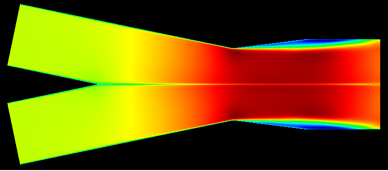
The figure shows contours of X-Direction Velocity. The most obvious loss sources here are the large separation regions (dark blue) downstream of the collector throat and the wake that forms in the mid passage from the boundary layer of the inner wall.
An obvious way to reduce the pressure loss is to reduce the wall slope on the expanding section of the collector. Here is a model of the baseline collector with half of the expanding wall slope:
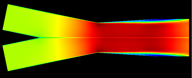
Overall, these are very similar results. The longer collector with the shallower wall angle has roughly ~2% less pressure loss than the baseline with no other changes. It also has a more uniform flow field in the center of the passage, caused by a reduced diffusion rate and less separation blockage... so definitely a step in the right direction.
I have ran several other simulations that I am still post processing, but I think we have already seen enough to influence our next collector design. I'll edit this post very soon with the results of the remaining designs

Edit - I thought I would add this one also. In this model I am starting with the baseline collector and the only thing I have done is added a 1" long constant diameter gap between the converging and diverging segments of the collector. The idea behind this analysis is that gains could be had by "turning" the flow in two steps as opposed to a single, large change in wall slope. In an ideal world, I would be able to use curved walls and fine tune the collector design... but such a design would have to be cast and would be a long lead, expensive item. By adding an additional segment to the diffuser we are trying to accomplish a similar effect...
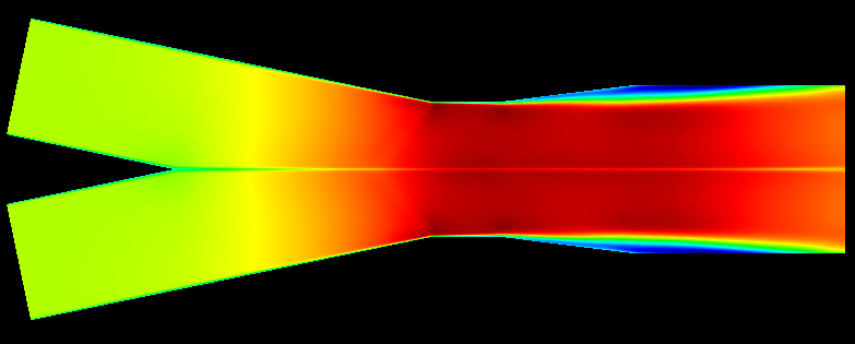
As far as losses are concerned, this model provides about a 3% pressure loss reduction as compared to the baseline... so even better than just reducing the wall slope
