Quote:
Originally Posted by serialk11r

Ah perhaps F1 engines have such high compression that they don't see quite as big gains. At the high rpms they run, cooling loss is pretty small, and they have extreme precision and advanced materials on their side, as well as practially restriction free induction and exhaust, so the advantage is perhaps not as big.
|
7% more 'free' power at their high levels is pretty significant.
Now back to induction...
(SolidWorks is for noobs)
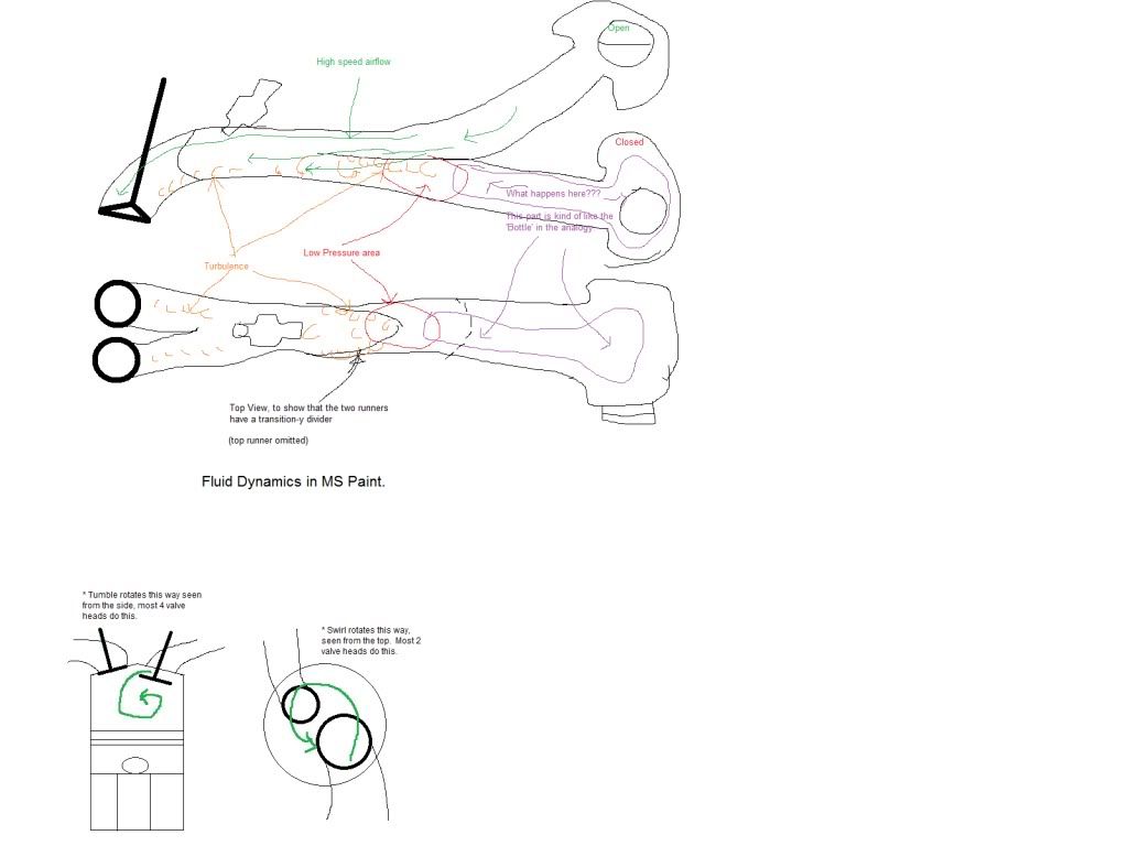
Okay, so there's my lovely diagram. (please ignore the accidental penis shapes, I didn't feel like re-drawing after I noticed...)
Now where was I? What I'm interested in is the merge area and the runner of the closed plenum.
In a similar application of a venturi merge collector in the exhaust, that low pressure area is used to make it easier for the next batch of exhaust gas leaving the connecting runner to exit the cylinder. This is inertial scavenging as opposed to the wave-type scavenging mentioned a few posts up.
The main difference between the exhaust merge collector and my dual runner idea is that at low rpm, the connected runner just stays closed.
What I'm guessing is that this will try to suck some of the upper runner's charge into the runner and cause some unpleasant turbulence. Part of this can be reduced by the way the two transition, flow likely trying to stay attached to the divider, and the fastest portion being kind of in the middle. But this is the part that makes me think of blowing air over the opening of an empty bottle (closed secondary plenum being the bottle). So could the turbulence and the low pressure area create vibrations/resonance that could be harnessed? And if so how?
The way the port flows, the turbulence being mostly on the bottom will not be that big of an issue as more than 50% flows over the 'top' side of the valves normally. So I may get a bit of 'free' low rpm flow because the velocity gains (yay!) will be on the 'good' side of the valve/port and the increased turbulence (boo...) will be on the 'bad' side of the valve/port.
I believe when Toyota/Yamaha did this on the original TVIS 4AGE the runners were side to side each runner aimed at its own valve. To me that doesn't make sense from a low rpm fuel distribution point of view. I would envision more puddling on one side than the other. But they may have been going for low rpm swirl. Still doesn't make that much sense since the angles should be already optimized for tumble at high rpm? Maybe just a packaging issue? (refer to epic diagram for difference between tumble and swirl if you don't already know...)
Next part is acoustic tuning (shudder...). I've got a basic idea of single runner wave tuning. But on this... I'm envisioning 3 reflection conditions.
First, The primary runner. Length, from valve to plenum.
Second, the secondary runner. Length, from valve to it's plenum (could be the same as primary or different).
Working with these two at high rpm, the pulse will leave the valve at the same time and then split down the different runners. Different lengths means the returns occur at different times. This could be used to tune for a flatter torque curve.
Now the next part is what happens at low rpm, with the lower plenum closed? I'm imagining that the two lengths involved would be the standard primary length and the other length I would guess would be from the intake valve to somewhat near the begining of the transition area because of a pressure difference? And/or maybe the entire length as well, once a wave starts bouncing around? Headache time...
Then there is moving things around with a dual VVT-i system... Variable overlap can change how big the time window is to get the waves into the cylinders, plus advancing/retarding can affect which/how much of the waves get used... Ow...
(PS Anyone have an idea what's the cheapest North American *Dual* VVT-i motor I could easily get my hands on? 2AR? Other brand dual cam-phasing motors?)