Sorry I haven't posted any updates for a while. I came down with a case of Shingles (very painful) and wasn't in the mood to do much.
But I'm over that now and have had lots of ideas swirling around in my head. I've mostly been focused on how to reduce the machining required to build the compressor. This will save time, money, and make this a more achievable project for more people.
The first step was changing the base compressor I was using for my base design from a Mitsubishi TD05/06 to a Garrett T70. The Garrett style compressor uses a backplate that is separate from the center portion of the turbo so it doesn't have to be recreated for the E-Charger.
Second I looked at how to connect the compressor wheel to the motor with a minimum amount of custom made parts.
The end result is a design which requires only one custom made mounting plate which is basically just a square with some holes drilled in it. Two of the turbo parts need to be reused and modified slightly but I have also made that as simple as possible.
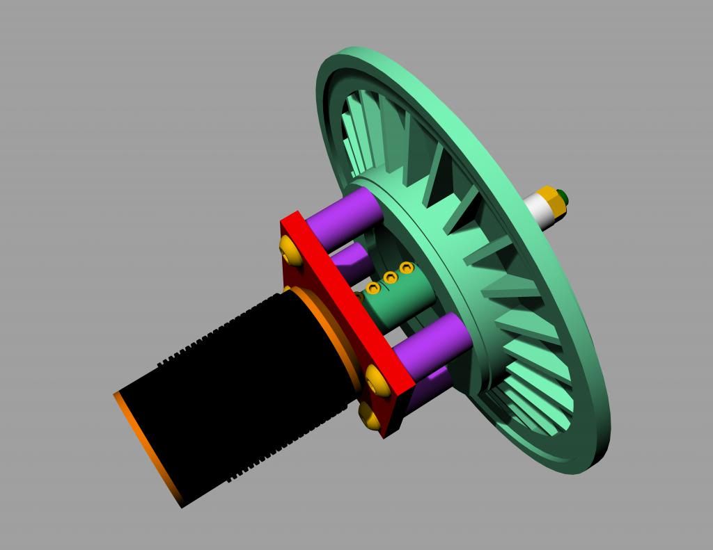
The CAD Design:
After acquiring a T70 turbo and disassembling it we modify the parts we will be reusing as needed.
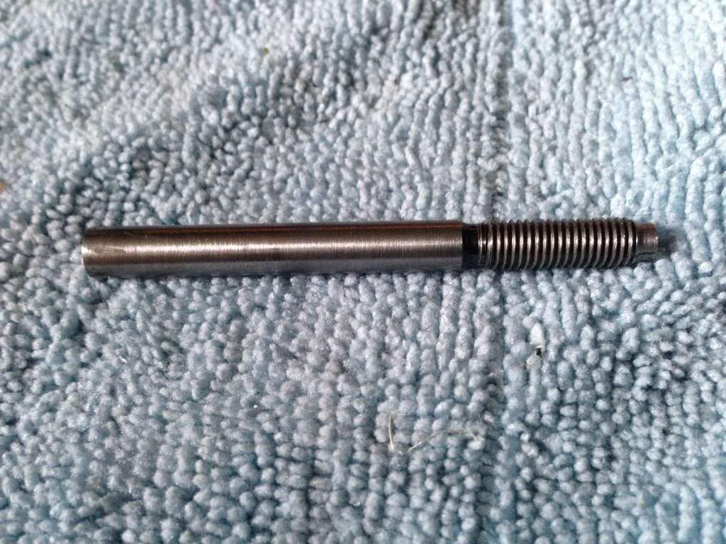
First we will need to reuse the shaft attached to the turbine wheel.
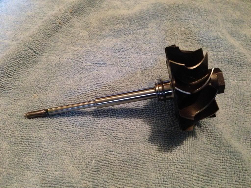
We only need the skinny portion so the rest can be cutoff and tossed. It's a hardened shaft so you have to grind it off. I did this in two steps in a lathe with a die grinder, but if you're careful you could easily do it with an angle grinder in one step. Just remember you need to keep all of the skinny portion so there can be little to no waste in your cut.
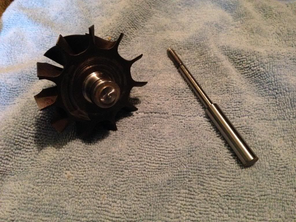
I did also have to de-burr the remaining portion and even out the diameter just a tiny bit.
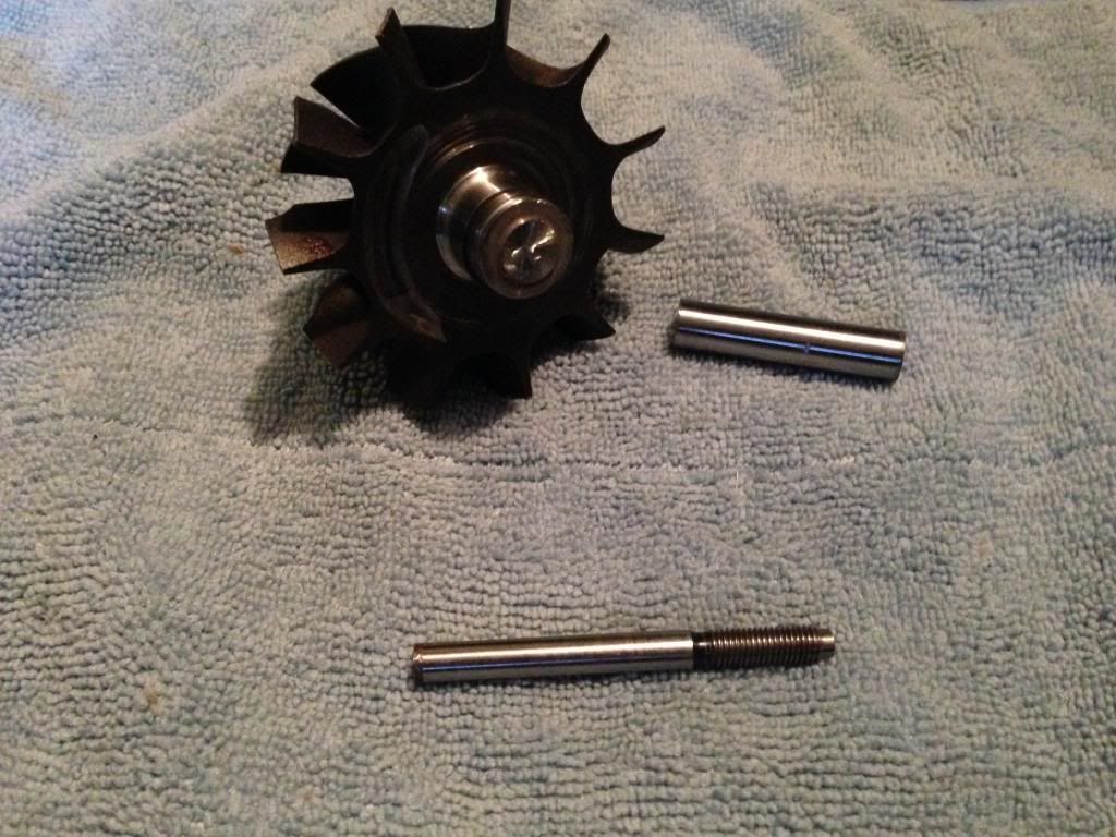
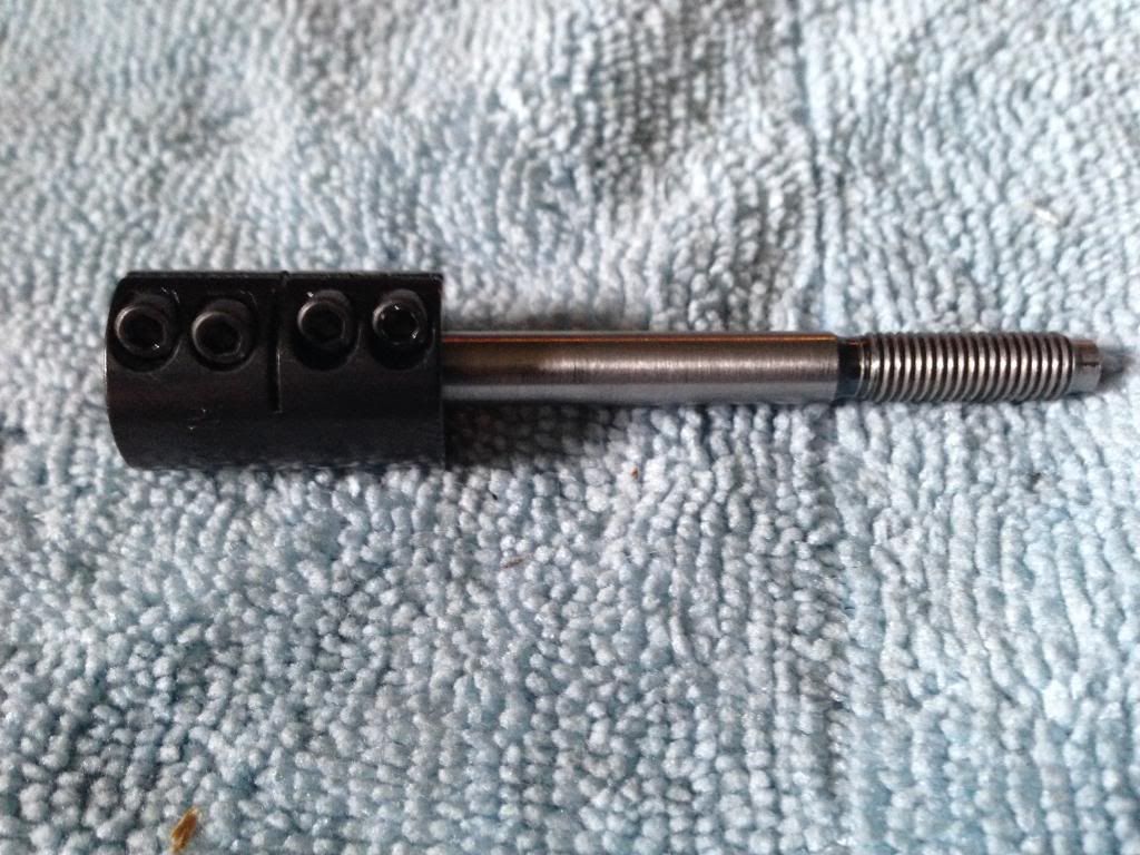
Next a coupler is added. It comes 1/4" in inch on the compressor side which is what we need. The motor side is 5/8" which is too small for the 5mm motor shaft. I used a 5mm reamer on the lathe to enlarge it. I suggest clamping the compressor side to something (I used a 1/4" drill bit) and then chucking that into the lathe.
Well then need to add a 1/4" spacer (1/4" ID, 3/8" OD).
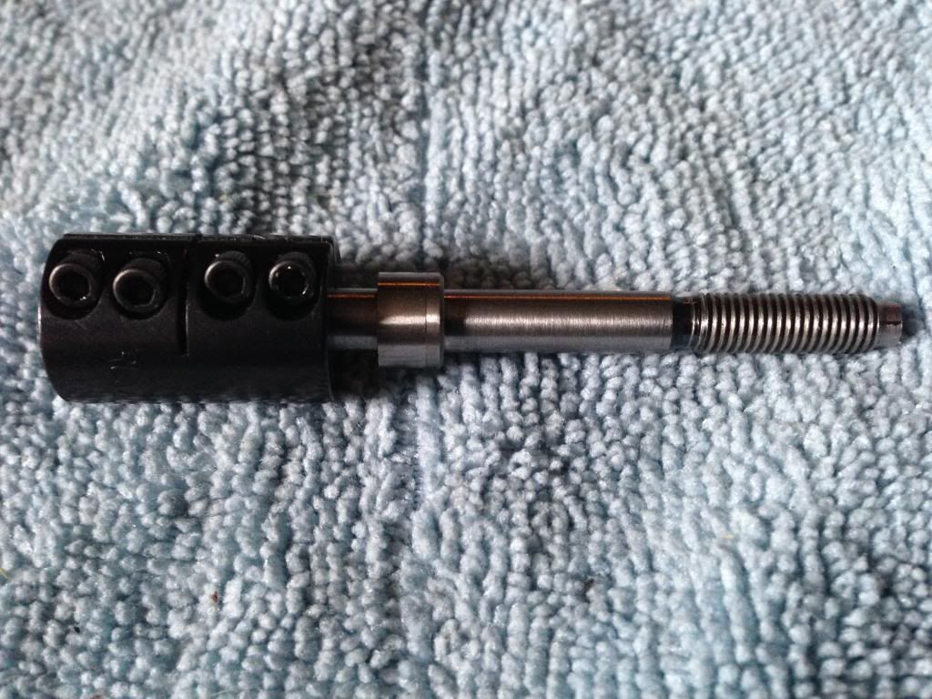
And a bearing (1/4" ID, 1/2" OD)
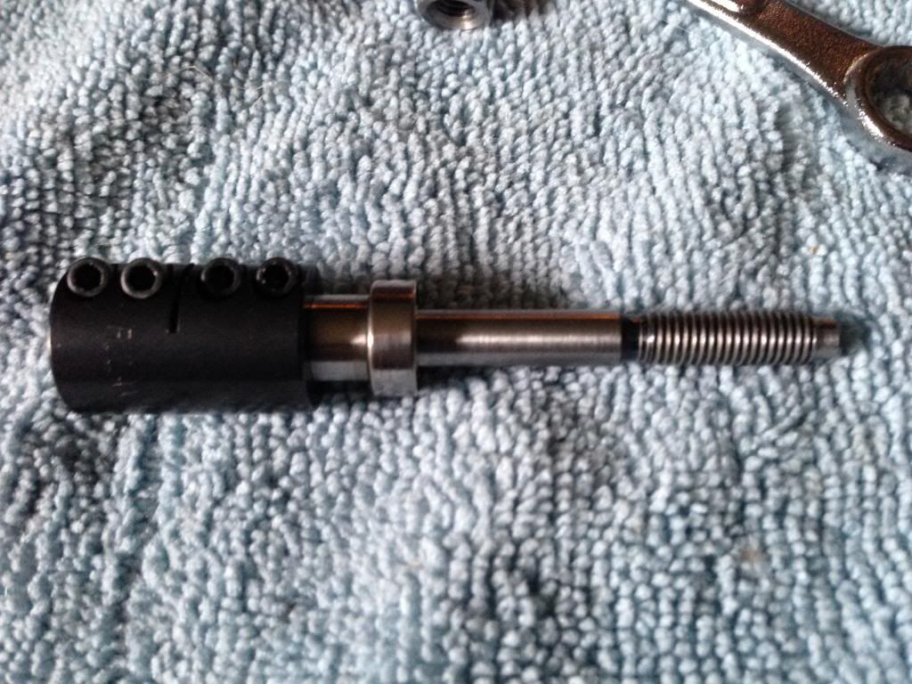
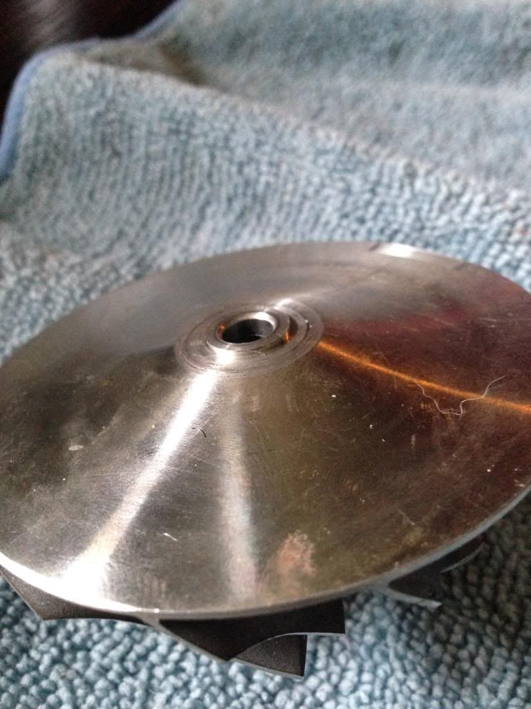
This is probably the trickiest step. You need to have the compressor wheel stand off of the bering so it touches the center hub, but not the outer edge. I did this by turning a small lip around the back of the compressor wheel. a washer of the right diameters could also be used but I had no luck finding one.
This is tricky you really need a lathe and some experience. If you want some tips let me know.
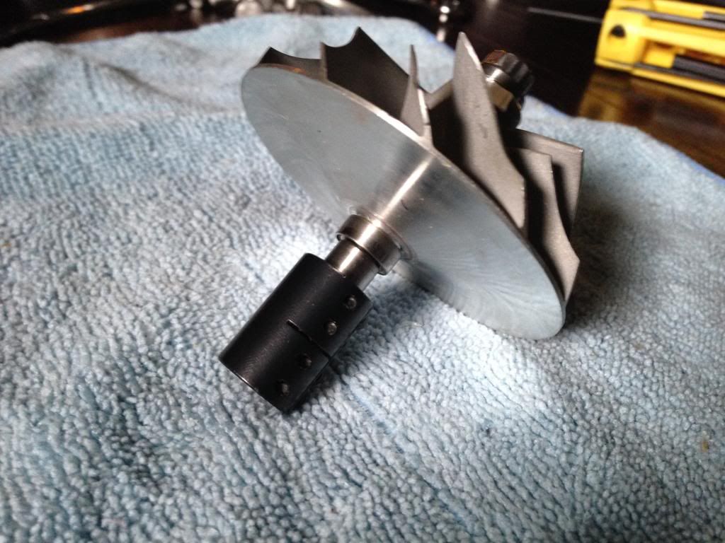
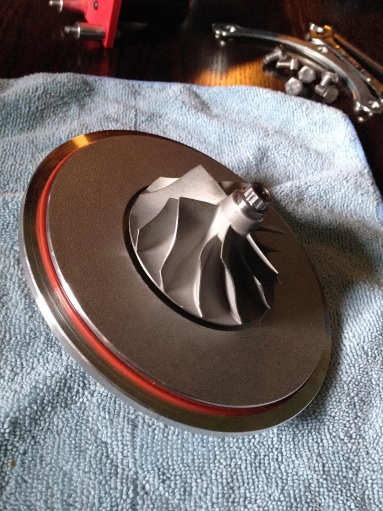
You'll need to add the compressor backplate before the compressor wheel goes on the shaft but here is a pic to show how the wheel/shaft assembly looks outside of the compressor housing.
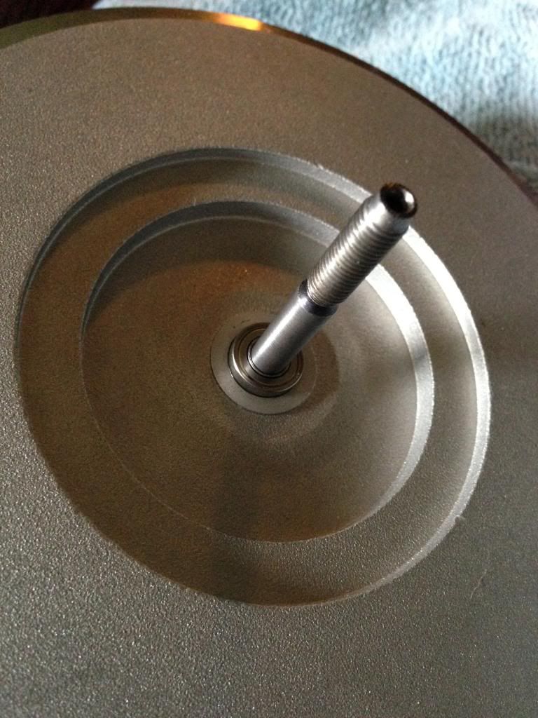
Now the shaft goes through the backplate. The 1/2" OD bearing fits perfectly in the center hole of the backplate providing support for the shaft as close to the compressor wheel as possible.
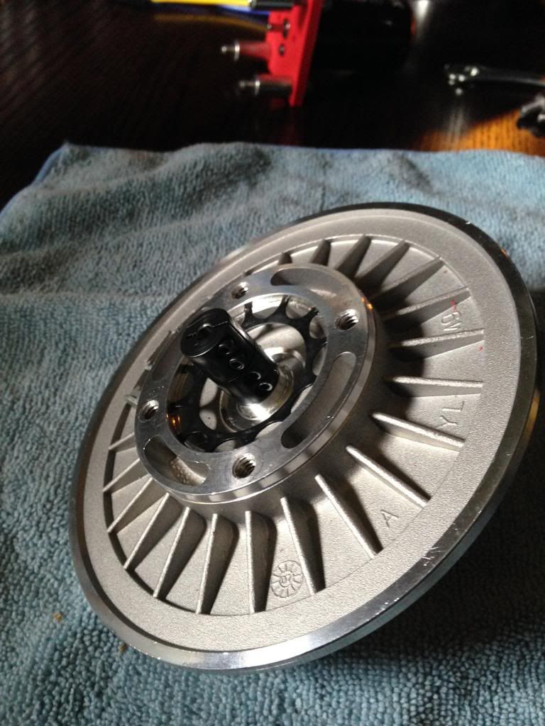
And then the compressor wheel is attached.
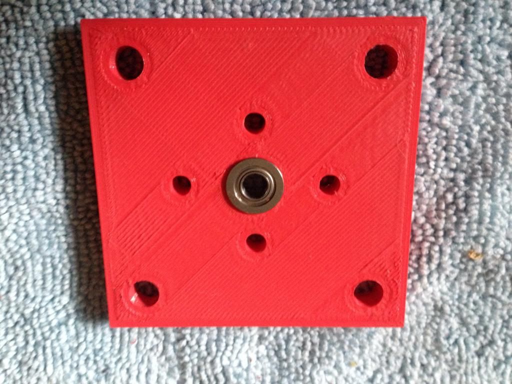
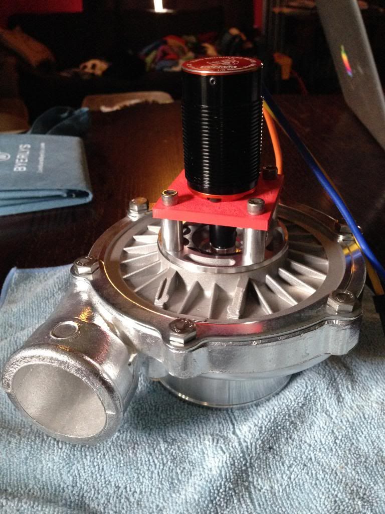
Now comes the custom part, the motor mounting plate. It's a simple 2.5" x 2.5" x 0.5" square. There is a center hole made to have a bearing pressed into it. I'm not sure it's needed but I thought it was better to have it.
There are four holes at the corners for mounting to the compressor back plate. I included two sets of holes for mounting the motor to give some flexibility on motor choice. One is 25mm and the other 30mm spacing.
I still need to machine this piece but for now I have 3D printed it. Once I make the metal version and check all my dimensions I'll post the design.
You'll need 1/4"x20 screws and 7/8" OD spacers to attach the mount to the backplate and whatever screws are appropriate for mounting your chosen motor to the plate. In my case I used 1.5" long screws, and 7/8" long spacers to attach to the back plate but you may need to go longer depending on your motor shaft length. You can't go shorter because the shaft coupler won't fit.
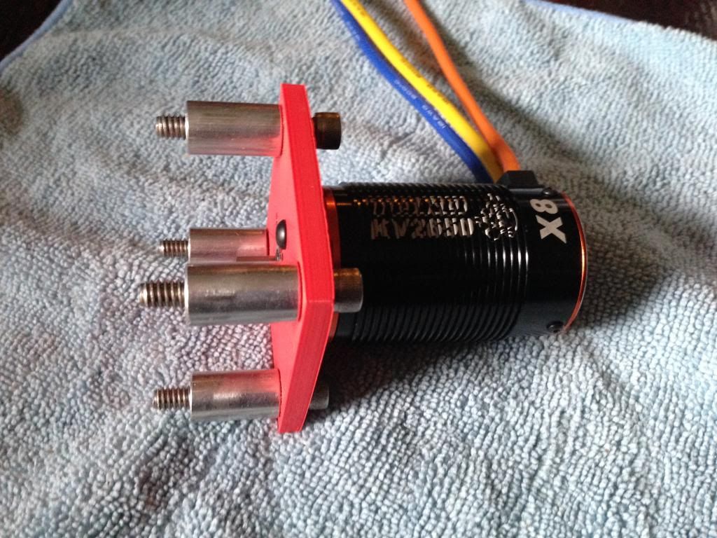
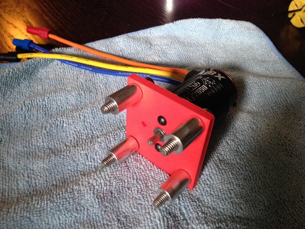
The last step is simple to attach the motor assembly to the backplate and tighten the coupling on the motor shaft.
Keep in mind that you will need to adjust the position of the coupling on the motor shaft to set the position of the compressor wheel in the back plate.
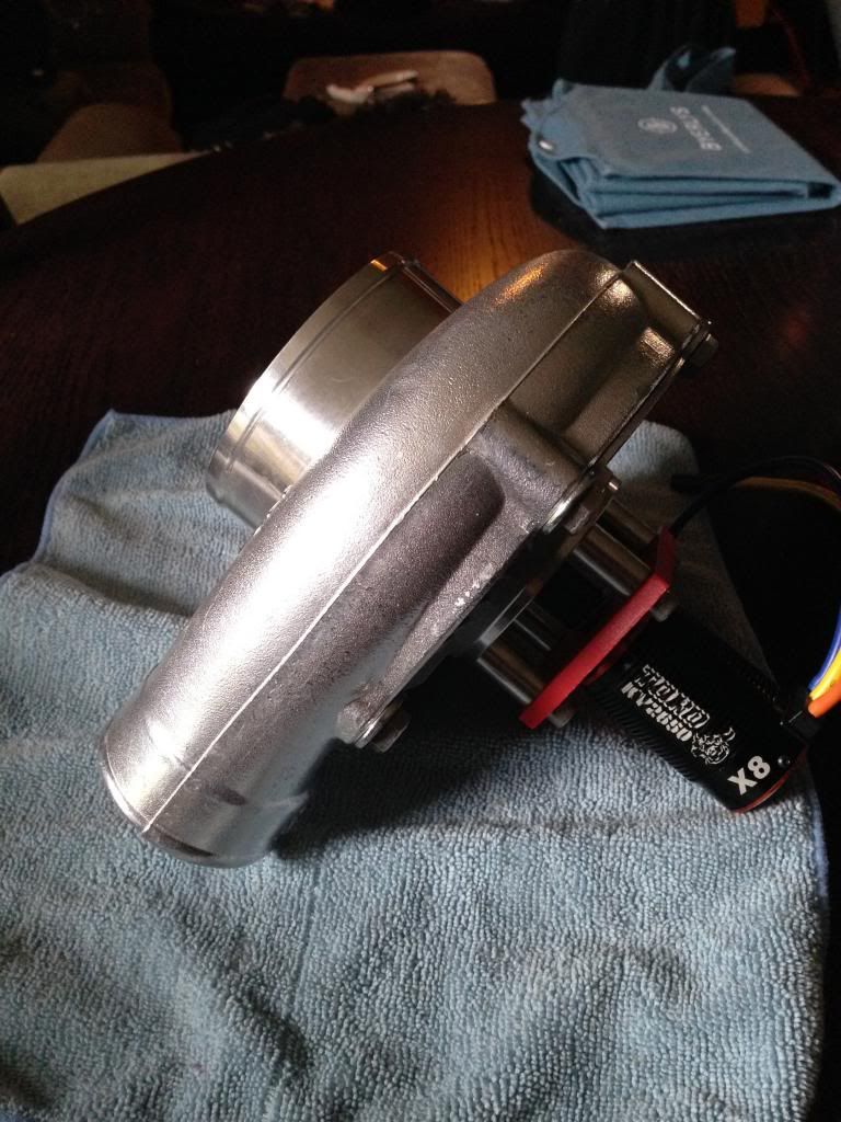
And that's it. I've only bench tested it at a minimum speed right now. I need to finish making the real motor mounting plate before I give it a real test.
I also have some concerns about the coupling. It's not designed for the kinds of speeds I'll be using it for, and I'm thinking it will need to be balanced so it doesn't shake the whole thing to bits.
Thoughts? Comments?