


|
||||||
| Electronics | Audio | NAV | Infotainment Anything related to in-car electronics, navigation, and infotainment. |
 |
|
|
Thread Tools | Search this Thread |
 05-06-2018, 02:23 PM
|
#1 |
|
A.K.A. Starlord

Join Date: Oct 2013
Drives: 2015 Series.Blue
Location: Illinois
Posts: 1,842
Thanks: 845
Thanked 2,099 Times in 834 Posts
Mentioned: 30 Post(s)
Tagged: 3 Thread(s)
|
Finished My Toggle Switches and Custom Wiring
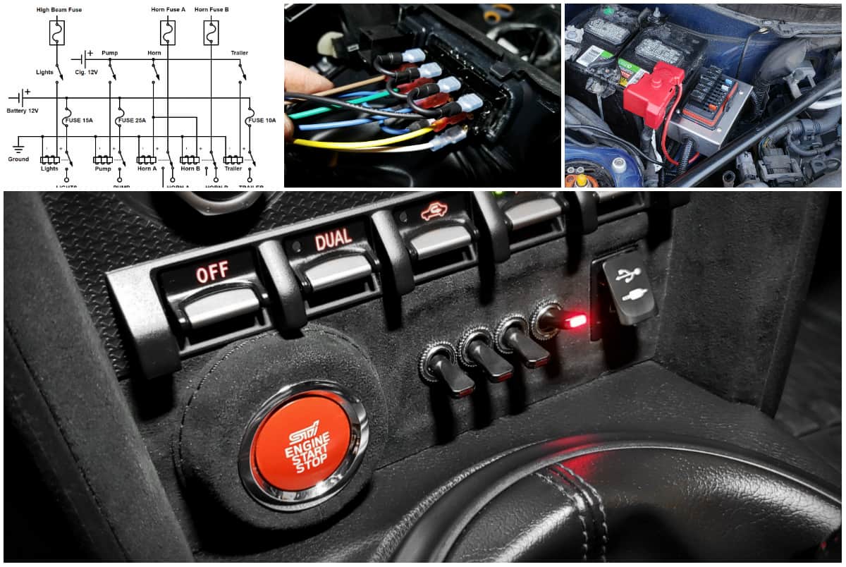 My Toggle Switches and Wiring I’ve owned the car for a while now, and one of the things that had been irritating me was that I was starting to accumulate wires from various projects running all over the place, and it was starting to piss off my OCD. Couple that with the fact that there are some more projects that I have planned which will introduce even more wires, and I decided that before I do anything else, I should get this wiring situation under control. This turned into a two-part project: 1. Create a custom toggle-switch panel to control existing, and upcoming parts, and integrate it into the dash. 2. Create a custom wiring harness that would consolidate and centralize wiring, and also take on a more OEM-style look. Making Use of a Useless Space Anyone with a Toyobaru is familiar with the little cubby hole on the center console, below the HVAC controls. It’s not particularly big, and it isn’t particularly useful considering that anything you put in there just slides out any time you accelerate. In addition, anyone with a Start/Stop button has the cubby size cut in half, rendering it even more useless. I figured that this would be the ideal location for the switch bank I was intending to add. With that decided, I headed off to the local Subaru dealership, and bought a second panel piece. The part number is 92126CA040, and it is surprisingly cheap (less than $7 from the dealership.) Keep in mind that part number is for a LHD vehicle. The first step was to fill in the opening. I mulled over several options, including creating a small “switch box” that I could slide into the pocket, but in the end I wound up using some 1/4″ thick Acrylic to plug the hole. The pocket itself tapers inward as it gets deeper, which means if you trim the acrylic to juuuuust the right size, it will wedge itself in tightly, and perfectly when you press it into place. As you can see from the photos below, once that was done, I cut away the rest of the pocket from the back. Then I filled the gaps with a combination of epoxy and superglue from both sides, and sanded the crap out of the edges until everything was smooth, and the curves matched the rest of the panel. 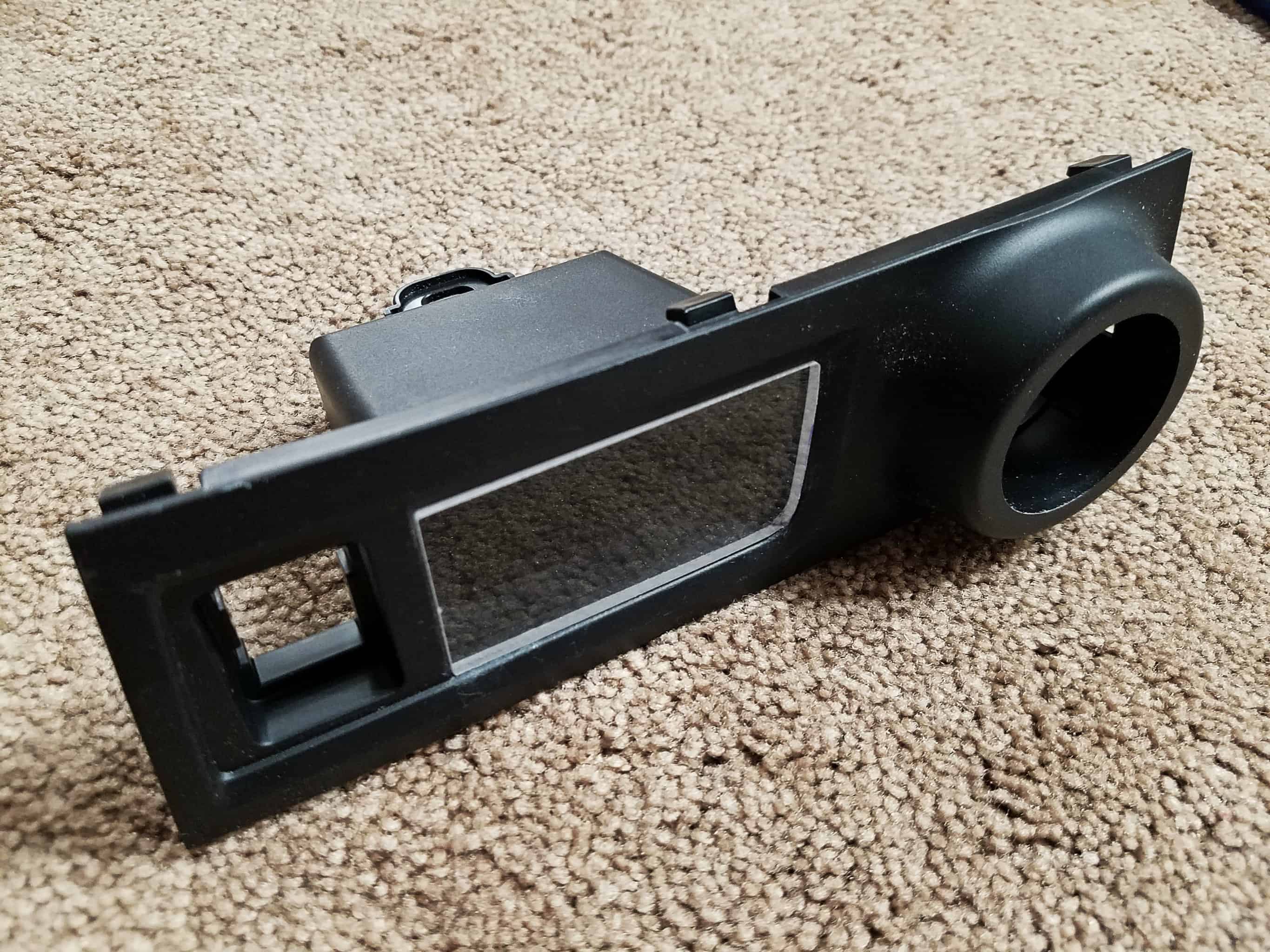 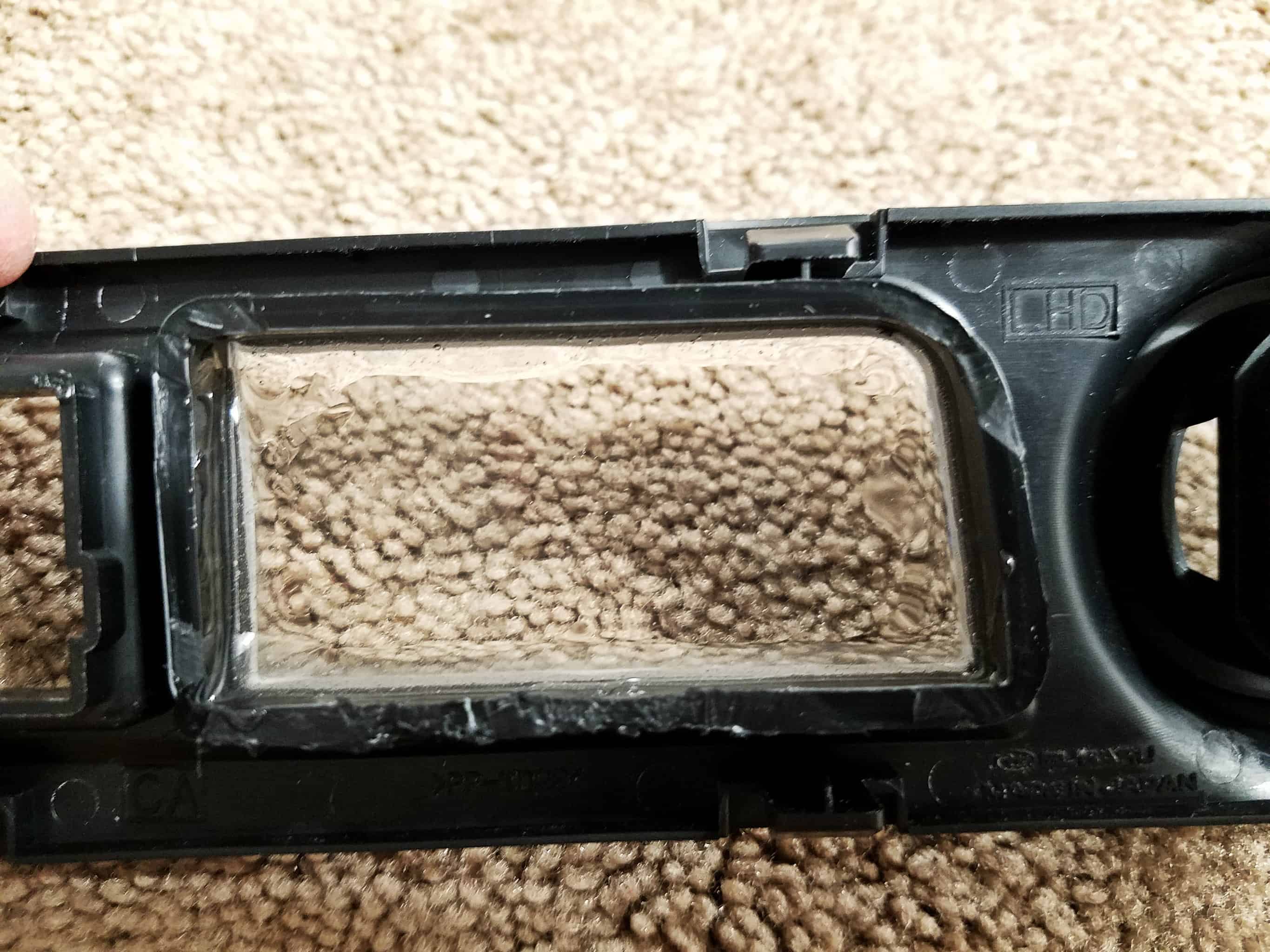 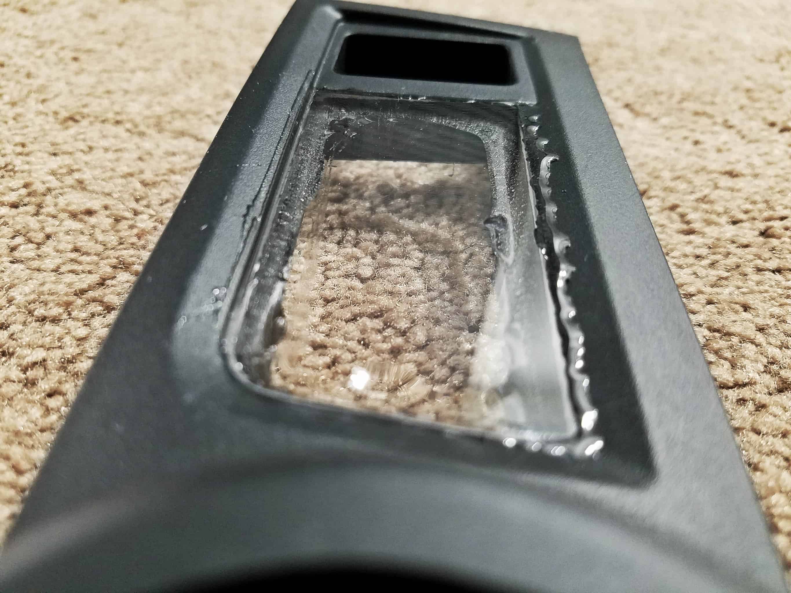 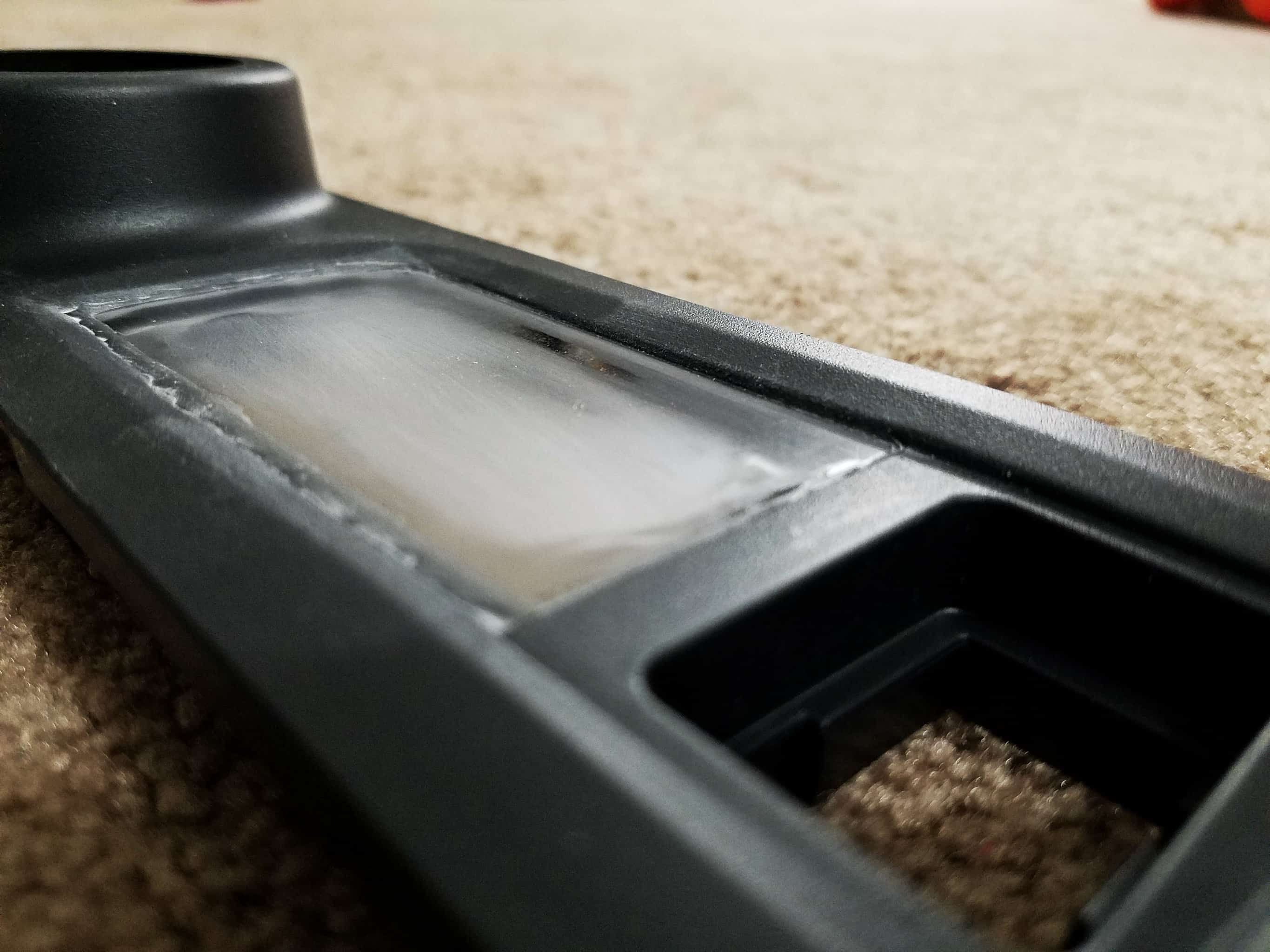 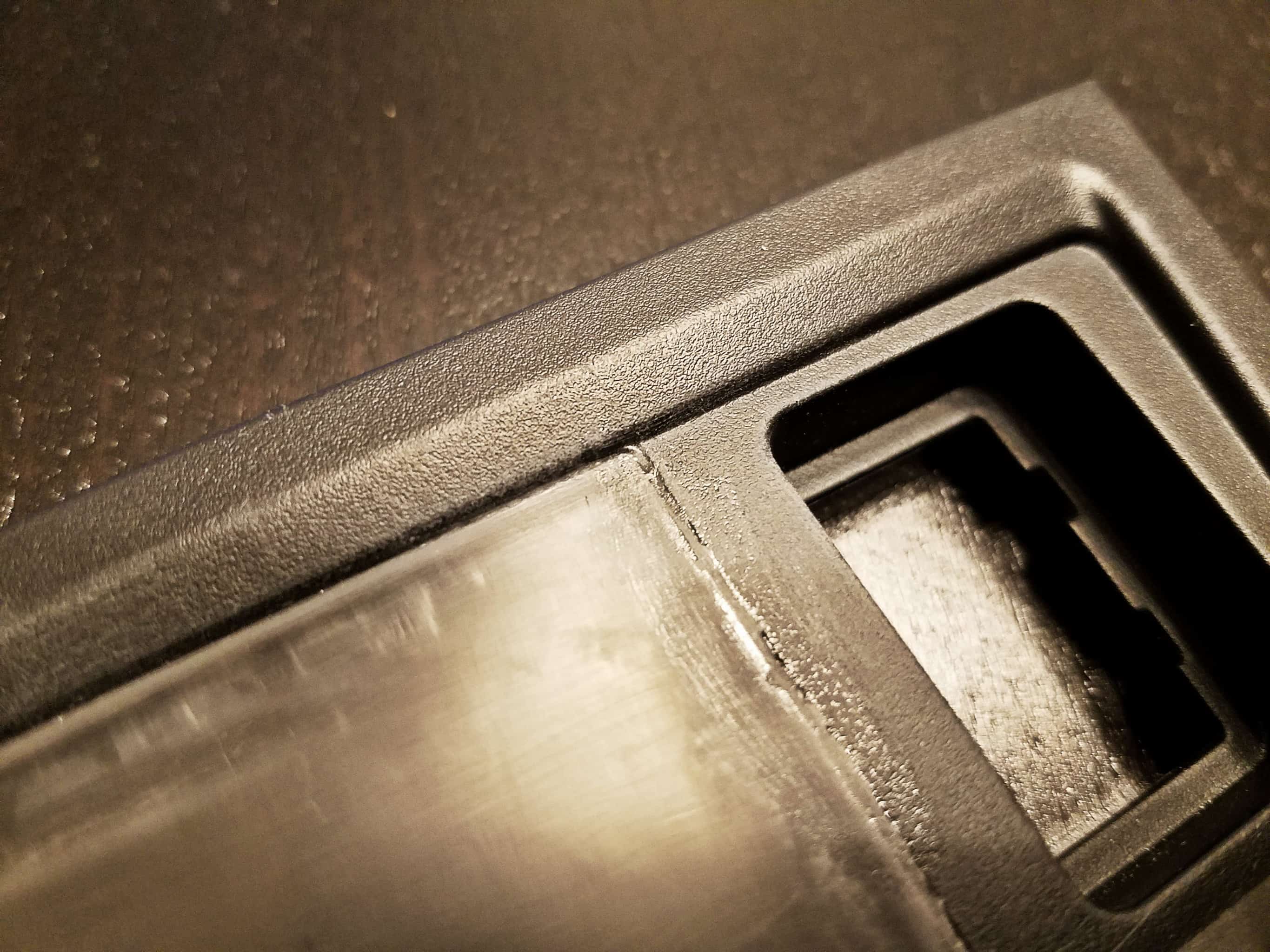 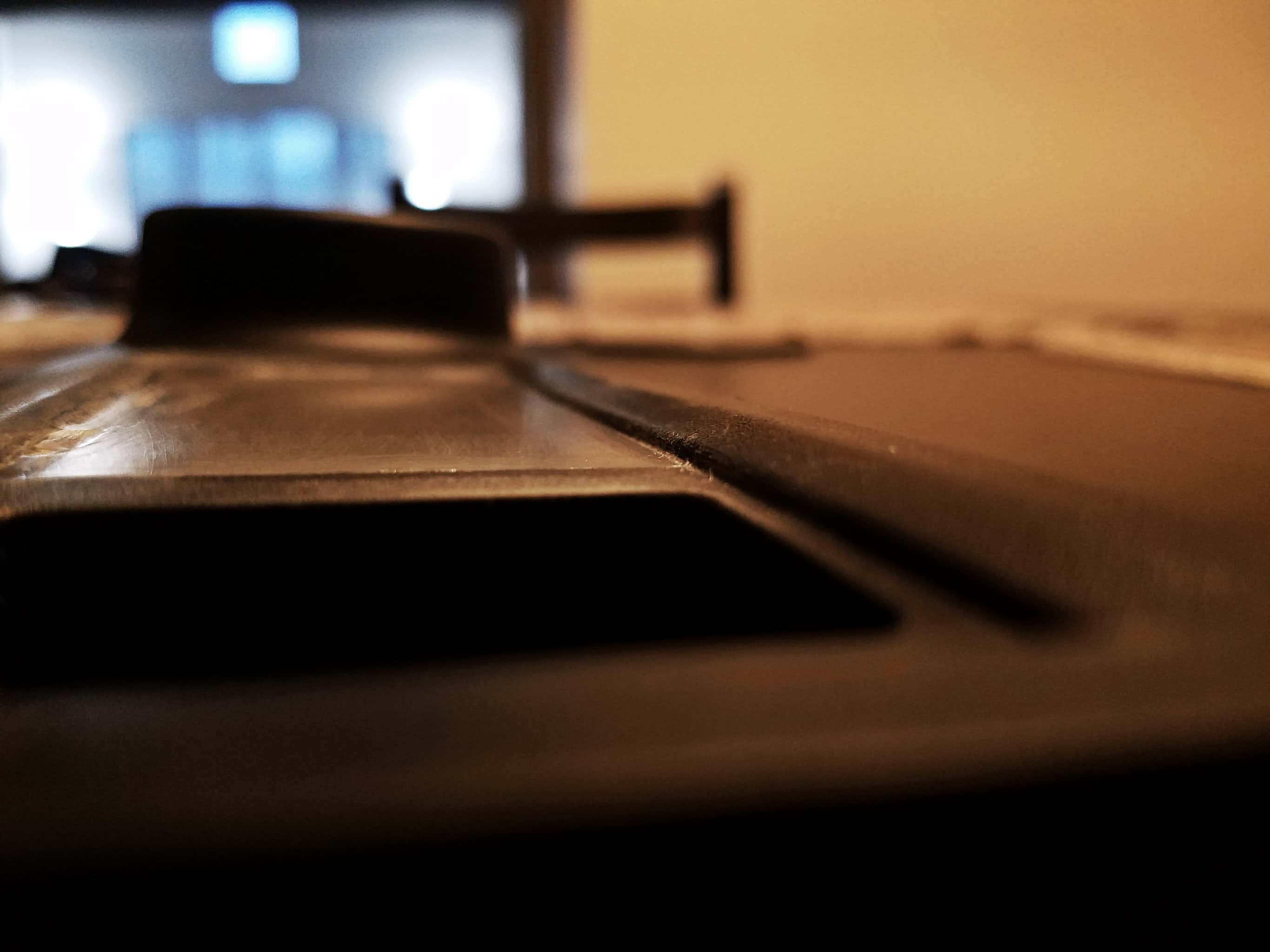 Toggle Switches For the switches themselves, I spent quite a lot of time trying to figure out what I wanted. All manner of fun options were available. Push button switches, rocker switches, etc… In the end, I went for a standard, RadioShack Red Illuminated toggle switch (Catalog #:2750024). I’ve used these switches before in past projects, and they are well-built. They also were narrow enough that I could fit four of them side-by-side in the small space I had available. I didn’t want the threaded “collars” of the switches to protrude from the face of my switch panel, so I went back and glued down a second 1/4″ layer of acrylic to make the panel face tall enough that the switches wouldn’t protrude more than 1-2mm – enough to thread on the lock ring. I actually bought a drill press for this project, along with a set of drill bits designed specifically for acrylic, because I had one shot at drilling all four holes in perfect alignment, and at a precise distance (I wanted the four switch bodies to be sandwiched together to add stability, and that required a very specific distance between holes.) I forgot to take a photo of the holes, but they came out perfectly. You can see some (kinda-blurry) photos of the results below. I had colored the acrylic black with a Sharpie to get a better sense of how it would look once it was complete. So far so good! 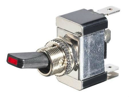 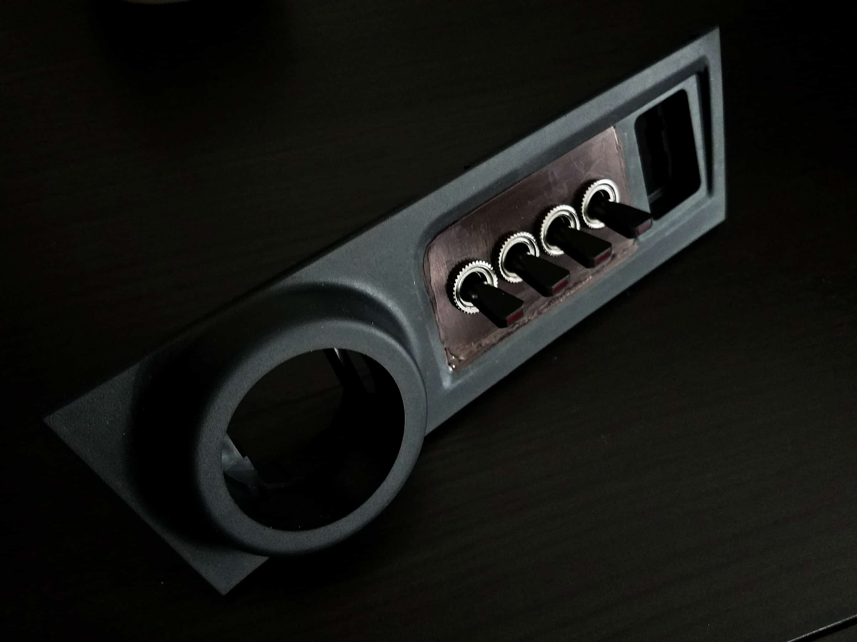 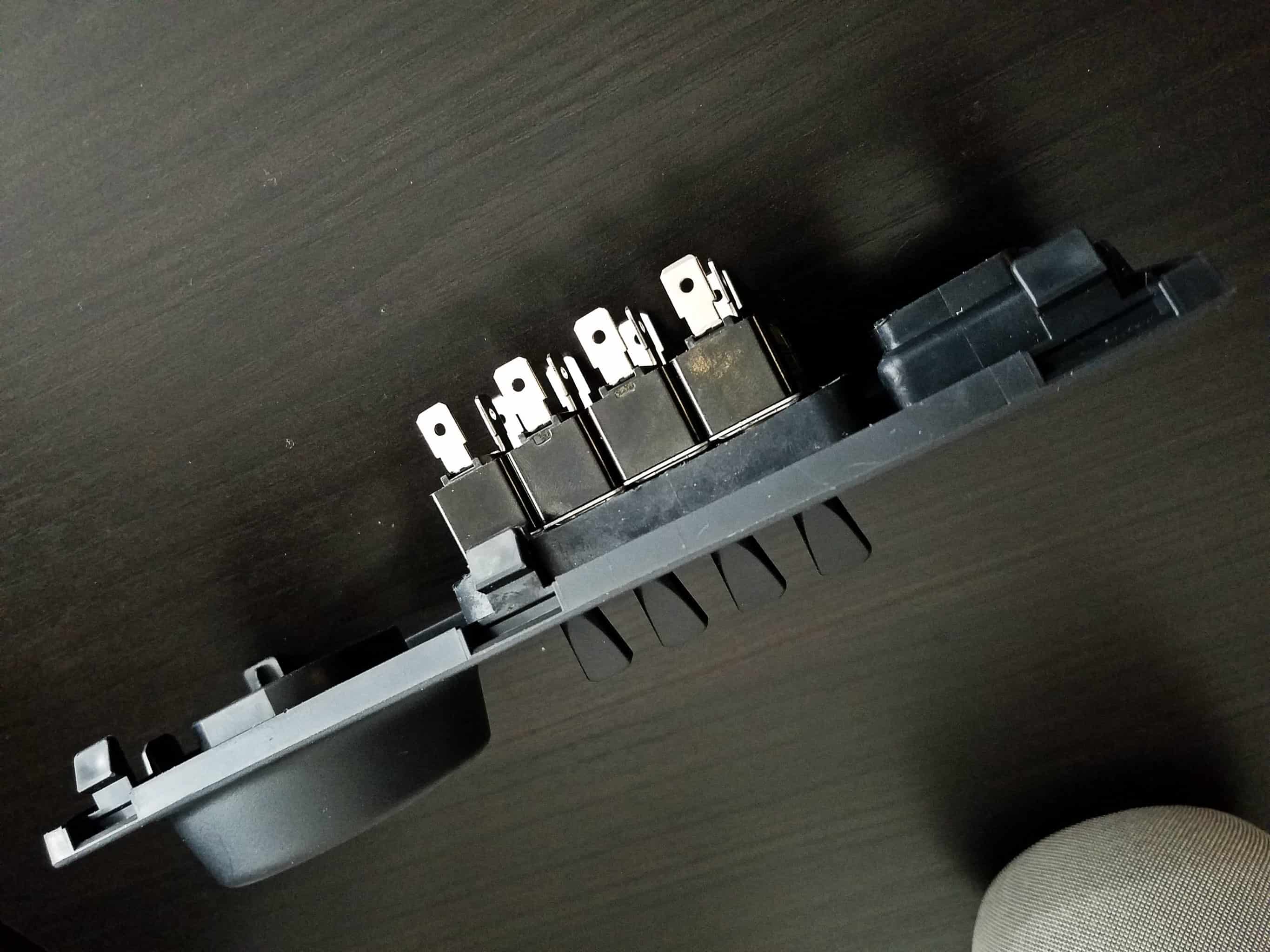 Alcantara by Sweidit! At this point, the only thing left to do was put some sort of finish on the panel. I briefly considered painting it, but I suck at properly painting things. I also considered wrapping it in Alcantara myself, as I had wrapped some simpler pieces, and those had turned out quite well (for example, the vertical trim pieces to each side of this panel.) However, the area around the Start/Stop button was not something I was going to be able to do properly myself. In the end, I farmed the job out to the guys at Sweidit, who I was eventually planning on working with for other parts of the interior anyway. They did a fantastic job of wrapping it, and also came up with a clever way of wrapping the steep curves around the Start/Stop button with a stitched-on “cap.” I think the results speak for themselves, but these guys are top-notch! Here’s what it looked like once I had installed my switches. 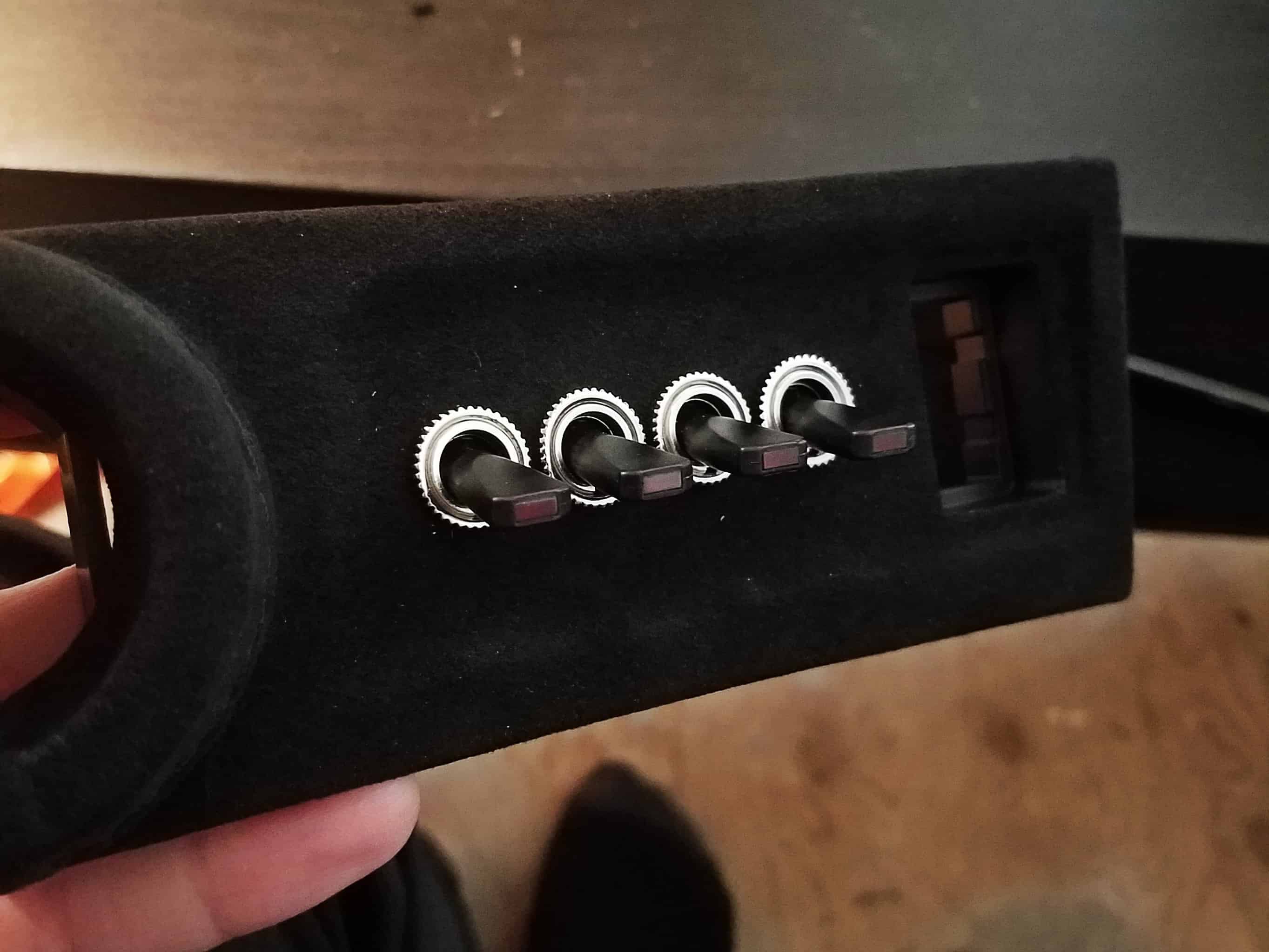 Relay and Fuse Block As the goal for this project was to consolidate and simplify as much wiring as possible, and also to wind up with an OEM-style harness to run various accessories, I began by searching for a suitable “fuse box” to house all of the main components. I eventually settled on a Bussmann 15303-2-2-4 Mini Fuse Panel. This box holds up to 10 fuses, and also up to 5 ISO 280 Micro Relays. It’s also waterproof, with a rubber seal on the top, and, since it uses Delphi metri-pack connectors on the back, each wire is also sealed from the elements. This was the perfect setup for what I wanted to do. Which, by the way, was to use my four toggle switches for the following:
5 relays was just enough for me to accomplish this task. The benefit to using this module is that I only need ONE power lead from the battery, and ONE ground lead to the chassis. Everything else would just be leads for the toggle switches, as well as power out to the various accessories. 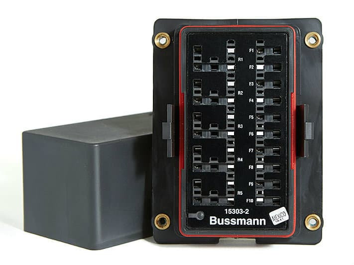 Wiring Diagram I’d never drawn up a proper wiring diagram before, so this was another new task for me. I’m not going to pretend for a moment that this is a “proper” diagram either, but it’s a hell of a lot more planning than I’ve ever put into any electrical project before. The only thing missing from these plans is that my switches are illuminated, and therefore have an additional ground lead coming from them. Every other wire, however, is represented here. The basic idea is as follows:
Power for the 2nd, 3rd, and 4th toggle switches comes from the fuse which powers the secondary power outlet in the car. This means those toggle switches are on switched power, which means even if I leave them in the on position, they will lose power when I turn the car off, preventing accidental battery drain. 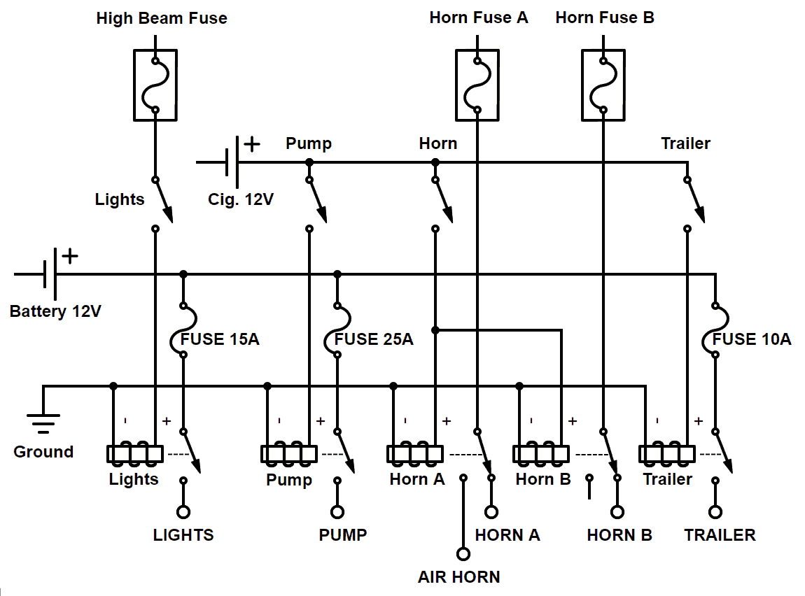 Building a Wiring Harness I have to say this was a LOT of fun. I’ve never built a wiring harness before, much less used all of these Delphi connector things, but it was kind of like LEGOs, and this really tickled my inner engineer. I did run into one issue before I even started, though. The Bussmann unit I bought came with an overlay sticker that blocked out one “unused” port on each of the 5 relay slots. However, this unused port was backwards with respect to the relays I had purchased. I just peeled that sticker off, and inserted the relays in the proper orientation without issue. I ordered all of the various cable seals, cavity plugs, crimp connectors, 30A relays (3 SPST, 2 SPDT), fuses, etc… that I would need, along with a crimp tool. For wire, I decided to buy the proper stuff, and ordered SXL wire of various gauges online. I love how flexible SXL wire is, and it’s just better-suited to automotive applications. The way the Bussmann unit works, is that there are two posts under the device. One of those is for power from the battery, which then feeds an internal bus providing power to all 10 fuses. From there, you can insert a Delphi connector to the other fuse slot, and run a wire wherever you like; either directly to an accessory, or just jump over to one of the various relays. Then you can take power from the relay to whichever accessory you’d like. The ground pins for all the relays are also bussed, and they all link up to the OTHER post on the bottom of the unit, which is where your one, single ground lead runs. The hardest part in all of this was simply keeping things straight as far as what wire needed to go where, what gauge it should be based on the intended application, etc… After a lot of careful work, I had my new wiring harness! 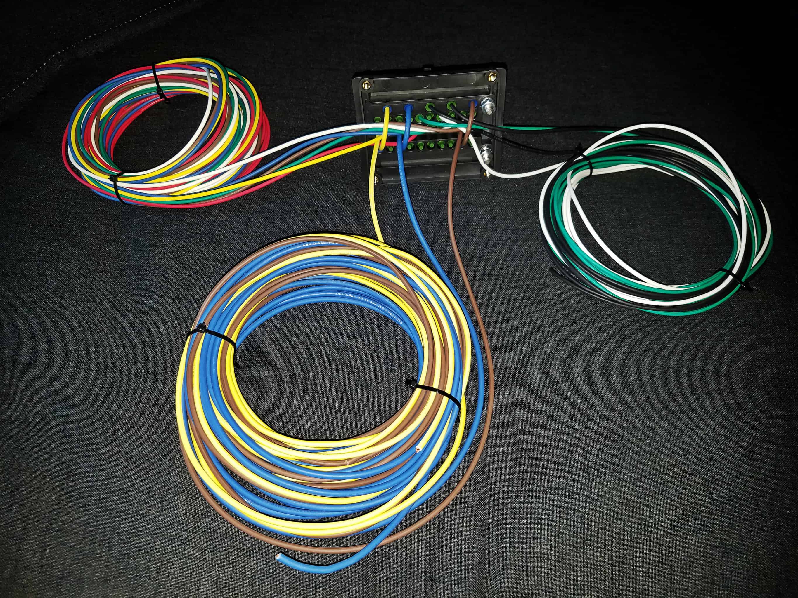 Installation So this is where things got tricky. I had decided early on that I wanted to mount the Bussmann unit near the battery, so I knew where in the engine bay it was going to go, but figuring out where to run all of the rest of the wires was definitely not an easy task. One set of wires needed to run to the front of the car. This was easy enough, as I was able to run them through the passenger side fender, and then run the wires down under the headlight into the bumper area. Then I had the set of wires that needed to run to the rear of the car. For those, I removed the battery, and sliced a hole in the giant grommet that already existed in the firewall. This allowed me to add my bundle of wires to the already massive bundle of factory wires. I then ran them under the door sill trim, and to the back of the trunk under the interior trim. Lastly, I had another bundle of wires that needed to reach the toggle switches in the dash. For this, I opted for a slightly unusual solution. I had always been meaning to remove the sound generator tubing in the engine bay, and I’m actually glad I hadn’t gotten around to it yet. What I did was remove the majority of the tubing, but left the last foot of it, along with the plastic elbow that plugs into the hole in the firewall. I re-purposed this as tubing through which to run those wires into the cabin in the passenger foot-well area, where it was easy to then route them up behind the center console to the switch bank. The plastic elbow had a little plastic cross inside of it that blocked the wires, but this was easy to drill out, as it’s very soft plastic. I love when the first drill bit you pick up happens to be an absolutely perfect fit for the size of the hole, lol. As I ran these wires, I also did something else I had never bothered to do in the past: I added proper loom to the wires just the way the OEMs do it. That meant adding the plastic ribbing, and then wrapping that in electrical tape. It definitely took some added effort, but the results were well worth it, because instead of having a ton of multi-colored wires in the engine bay, you just have a few, black wire looms that are indistinguishable from the stock wiring, apart from being clean and shiny. And beyond the looks, it obviously provides proper protection to the wires. 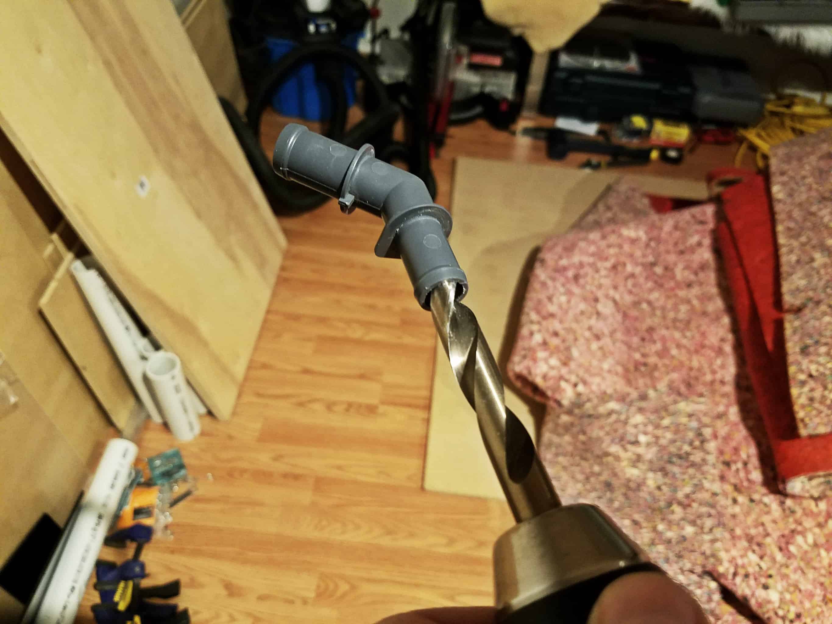 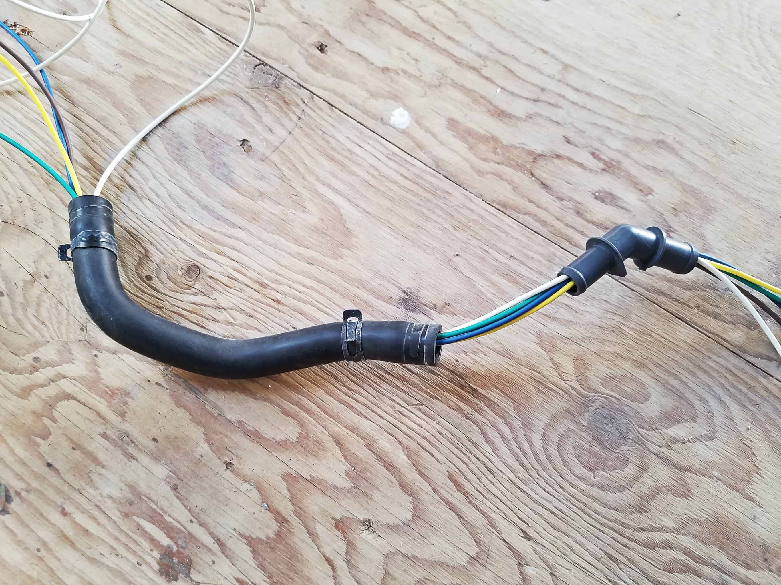  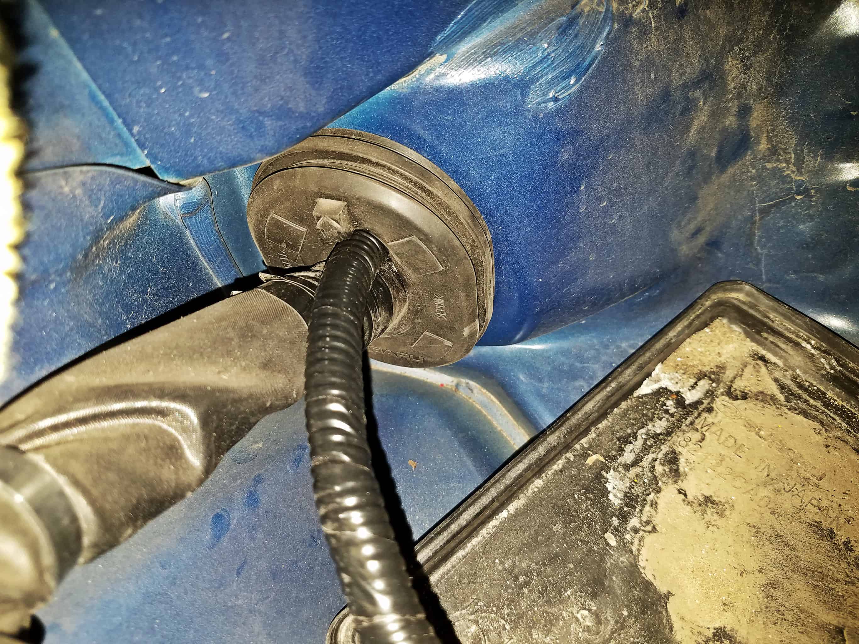 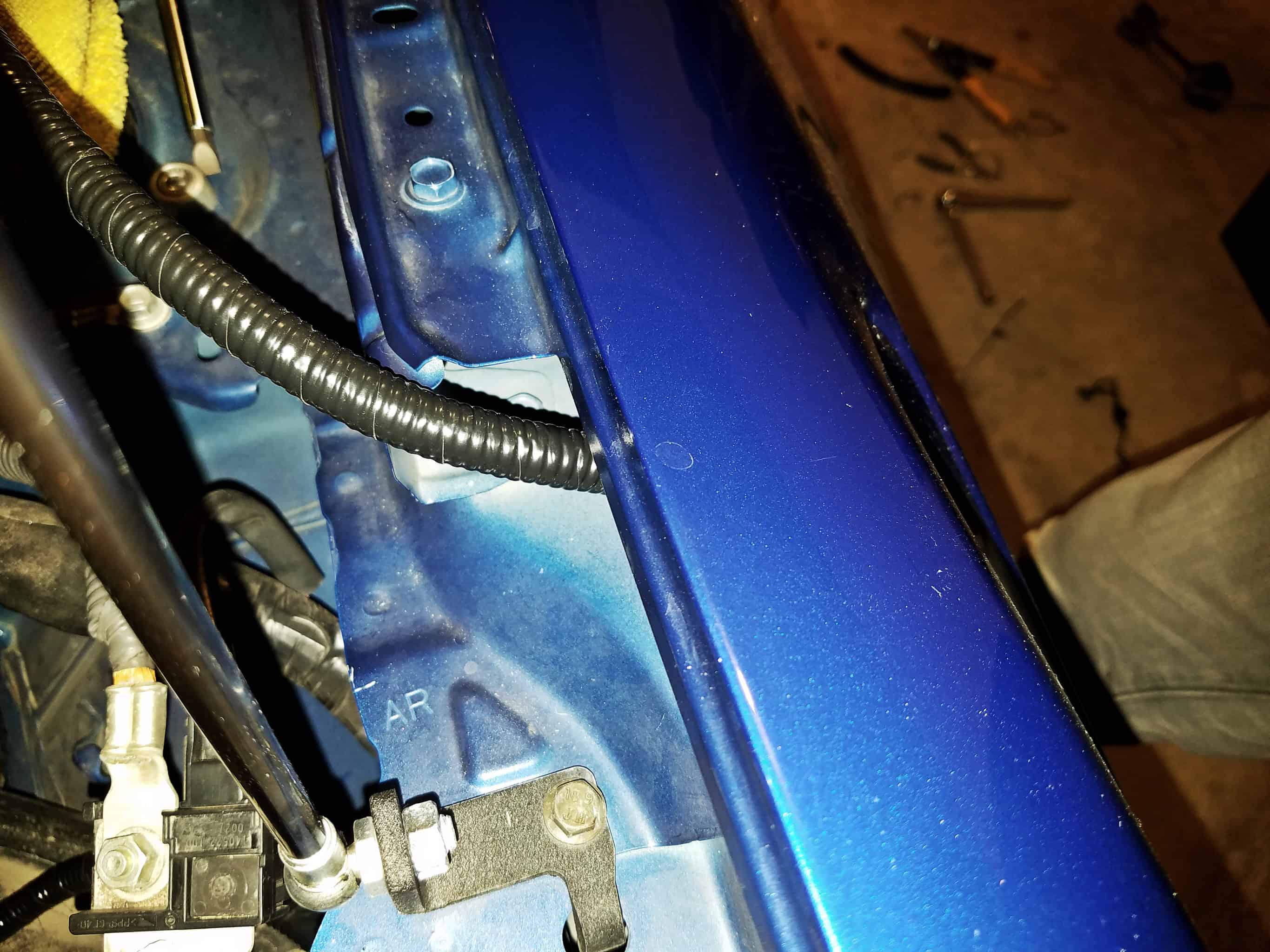 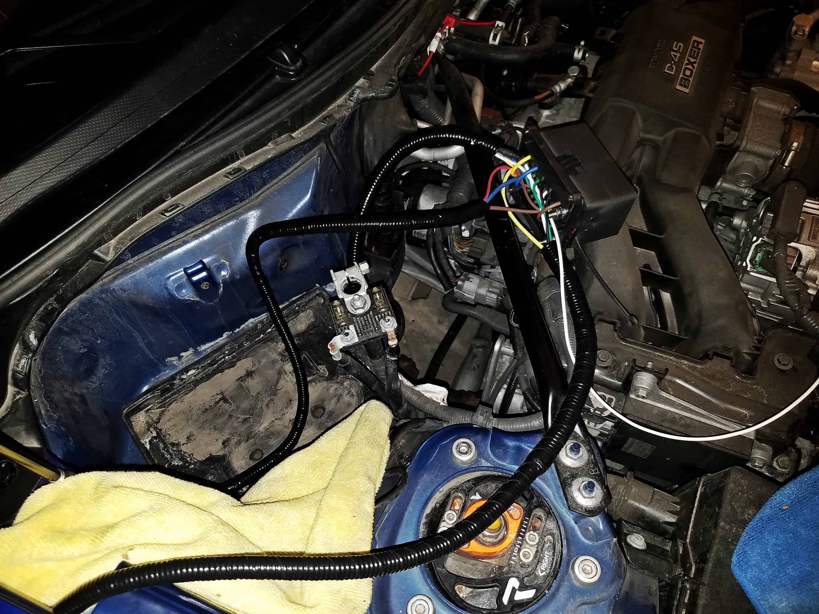 Making Ends Meet With all of the wiring spread throughout the car, it was time to start connecting everything together. I used an add-a-fuse adapter to connect the lead from the high beam fuse in the fuse box in the engine bay. I sliced out a very tiny slot in the base of the fuse box right under the cover to allow the wire to pass through while still allowing the fuse box cover to close properly. The leads running down the fender to the bumper were for both the horns, and the light bar. I don’t have the light bar yet, so that wire is currently coiled up and zip tied out of the way, but it simply needs to be connected once I install that. The horns were a bit more involved, and they’re the only part of the car that I have permanently modified. I cut off the connectors going to the horns, and instead connected those wires to the leads going back to the relays in my fuse box. From there, I have two wires going back down to the horns. I spliced the connectors I had cut off onto those wires instead, and plugged those into the horns. So basically I inserted those two SPDT relays into the circuit, allowing them to interrupt and redirect that horn signal when I flip my switch. Wires running to the rear of the car were either tied off (for the air horns and compressor), or in the case of the trailer harness, connected to the power module. That left just the wires for the switch panel itself. This was definitely a complicated little project. The switches have three leads each. They need a power source, then there is the accessory output (the relays, in my case) and also a ground, which is needed because they have LEDs. Power for the light bar switch is fed from the high beam fuse. For the other three, I wired them together, and then ran that wire to another add-a-fuse connected to the Power Point #2 fuse in the fuse box in the driver’s side footwell. This gave me the switched power I was looking for. I also wired all of the ground leads together, and grounded those at the bolt securing the bottom of the fuse box. Then I connected up the leads passed through the sound generator tube. One thing I haven’t mentioned yet, is that the back of the pocket on the stock trim piece has a clip, into which one of the interior key fob antennas is secured. Having cut off this pocket, there was no place left to snap that antenna into place, so I simply oriented it in the same position, and zip tied it securely to the wires themselves. That done, I was able to button everything up, and fully install my new trim piece. I am super happy with how it turned out. It looks great, and it matches the Alcantara parts I had wrapped myself. 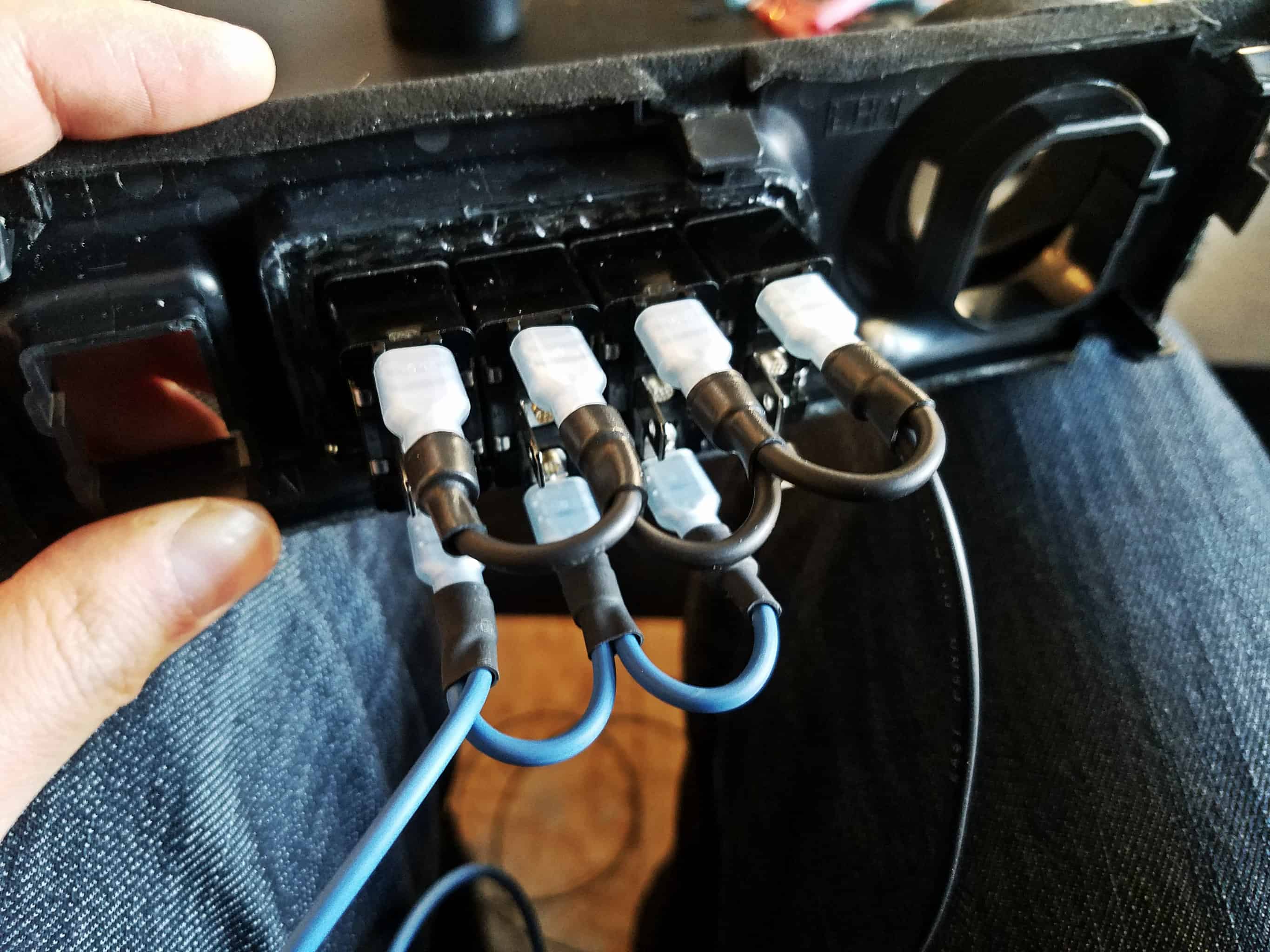 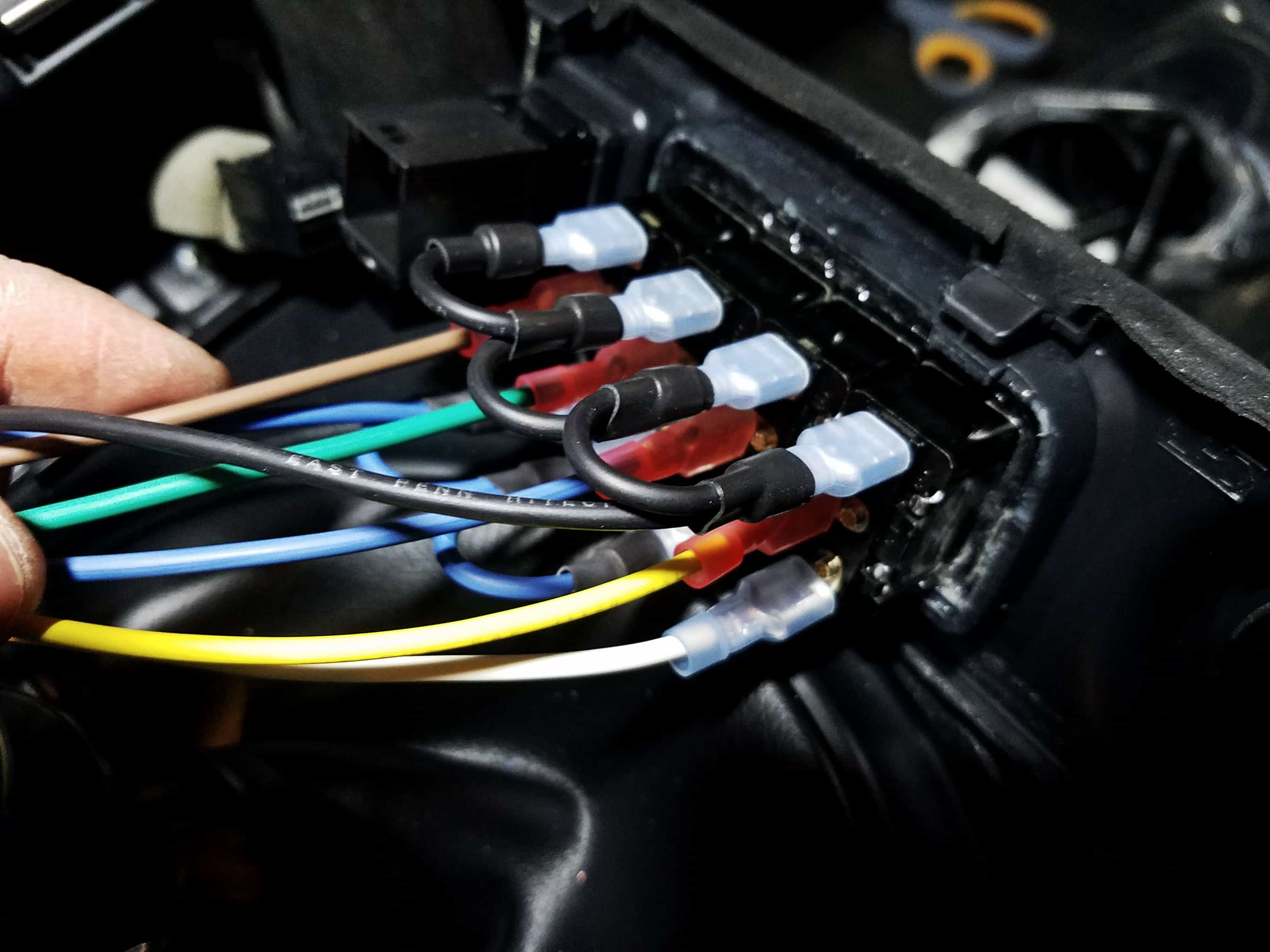 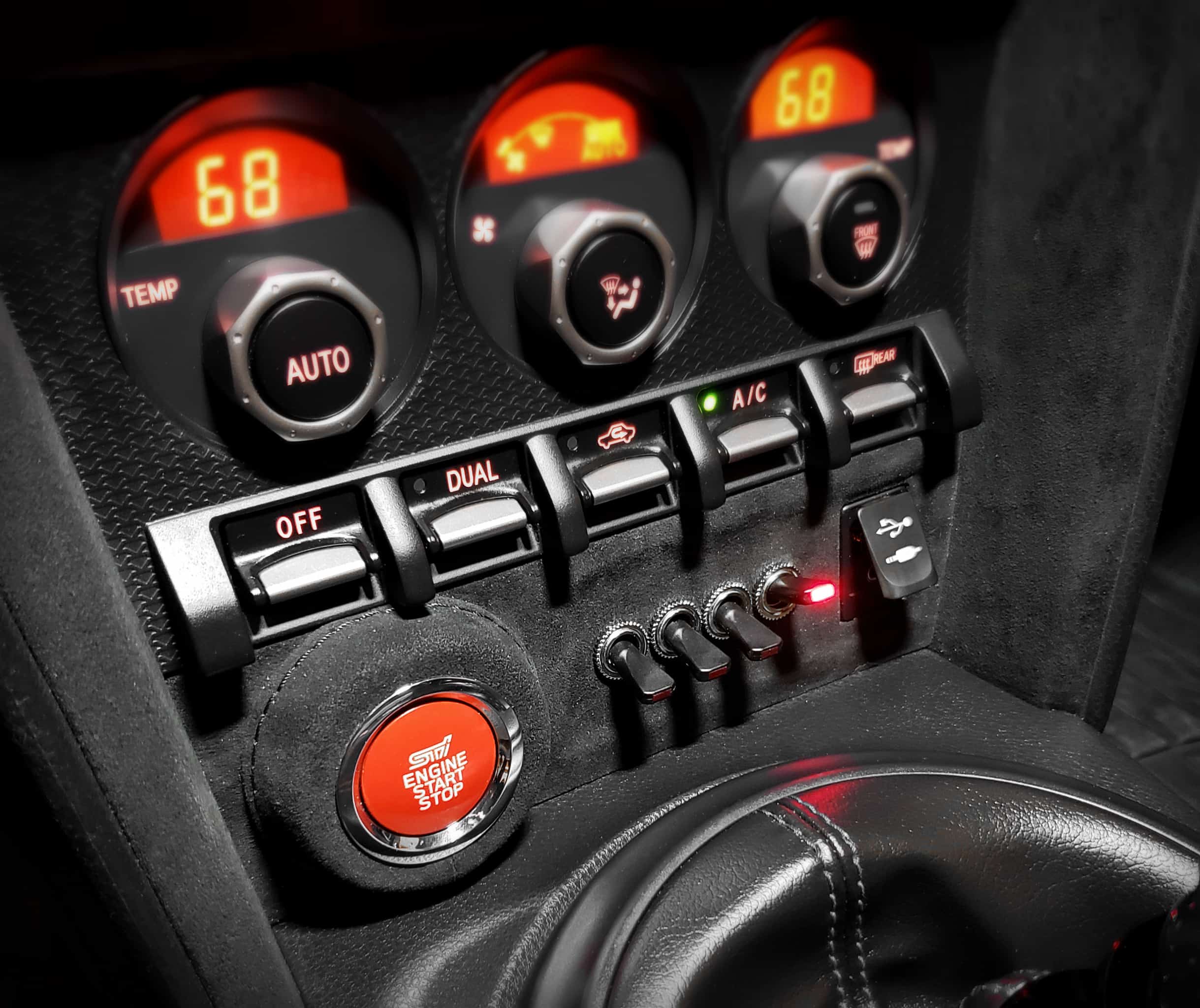 Designing a Custom Bracket At this point, everything was functional, but there was one matter left that I needed to address: how I was going to secure that Bussmann unit in the engine bay. At the moment, it was just temporarily zip-tied to the strut brace, and the battery, leaving it to flop around, and this was only a temporary solution until I could figure out something more permanent. I came up with a few different solutions – most using the strut brace as part of a mounting solution, but none of them seemed particularly elegant. There were no really good mounting places in that part of the engine bay to which I could easily mount the box. Then I had an epiphany, and realized I could easily use the battery itself to hold a bracket in place. So I took a bunch of measurements, and drew up this bracket in CAD that would sit under the battery. It would provide a face to mount the Bussmann unit, and with the sides folded down, would cover up the wires coming out of the back of the unit, for a nicer aesthetic look. I added cut-outs on each end of the Bussmann unit to allow for some of the wire looms to pass through (I would add a rubber grommet to hold them in place.) I struggled to find someone who could make this for me without it costing an arm and a leg… but then my girlfriend pulled through with someone who was able to laser cut it on a CNC out of stainless steel, and bend it. He wound up making me TWO of them for good measure, and it didn’t cost me a dime! What a nice man! I was happy to discover that all of my measurements came out basically perfect, and the unit fit “like a glove.” With this installed, that was the last step in the project, and I think it looks fantastic! 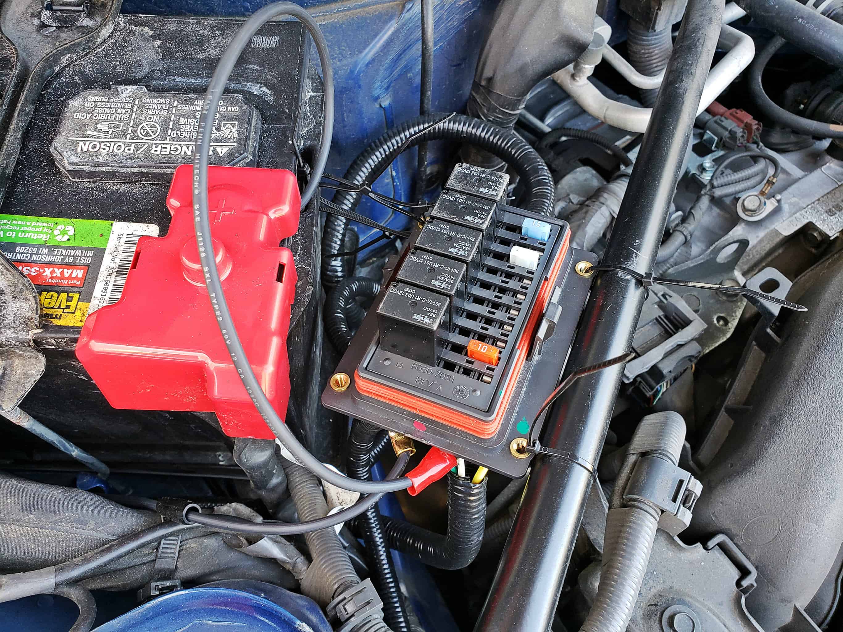 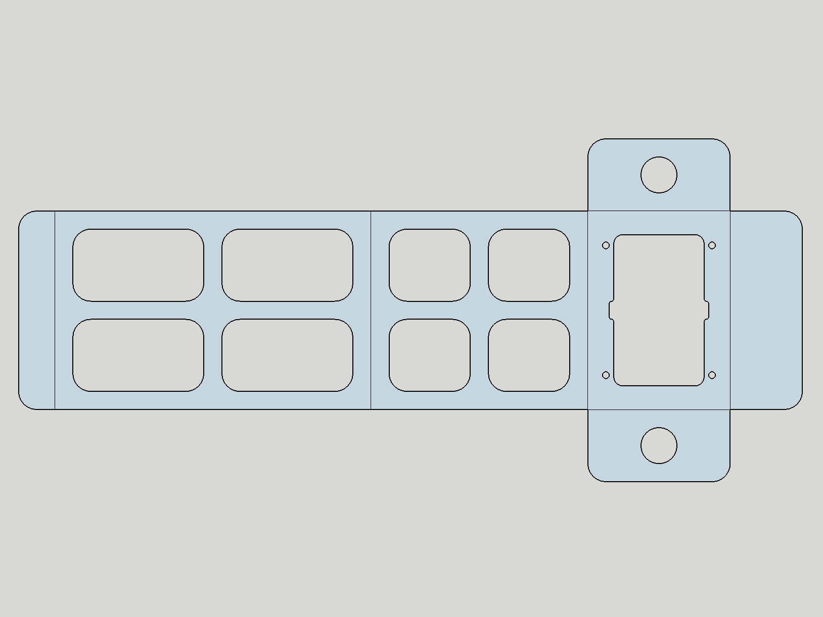 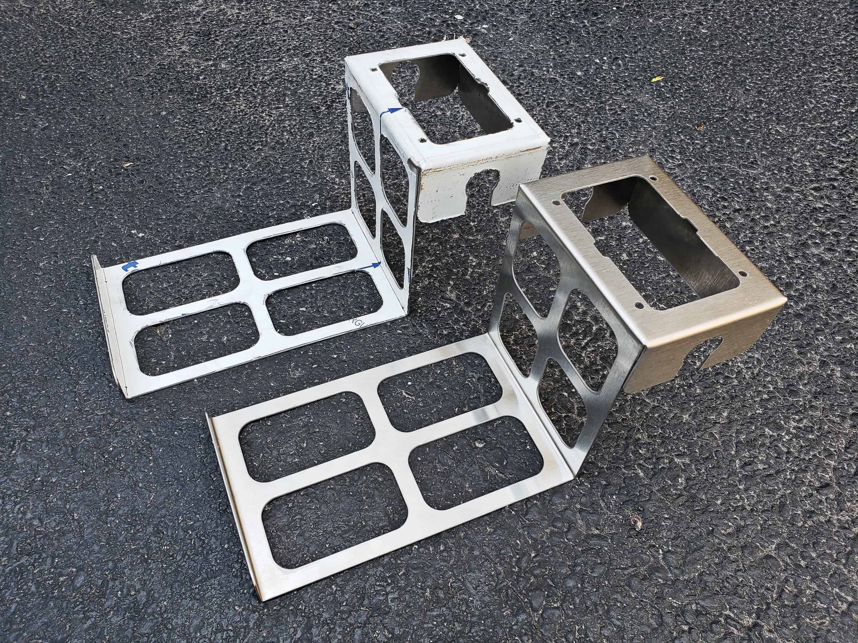 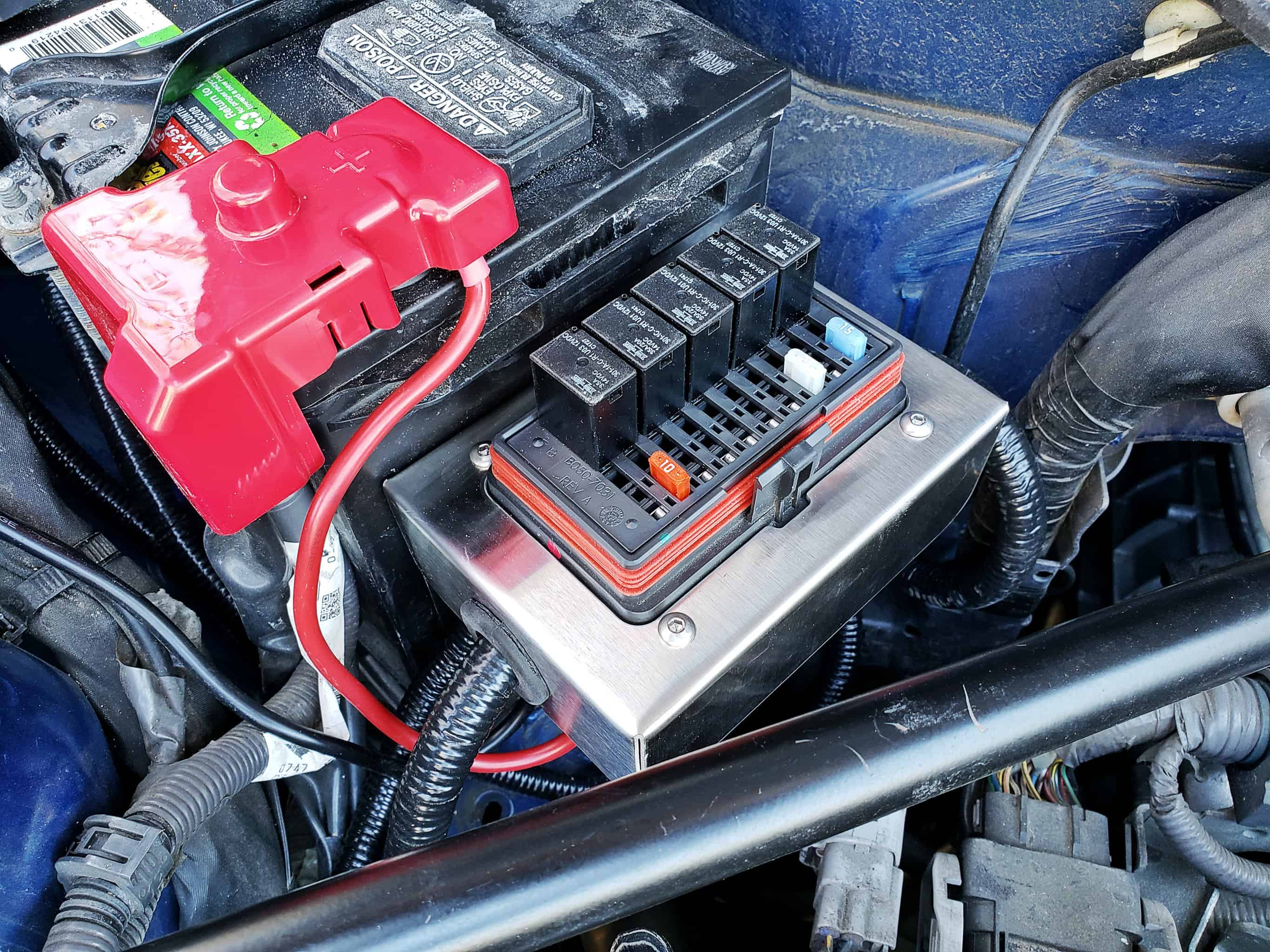 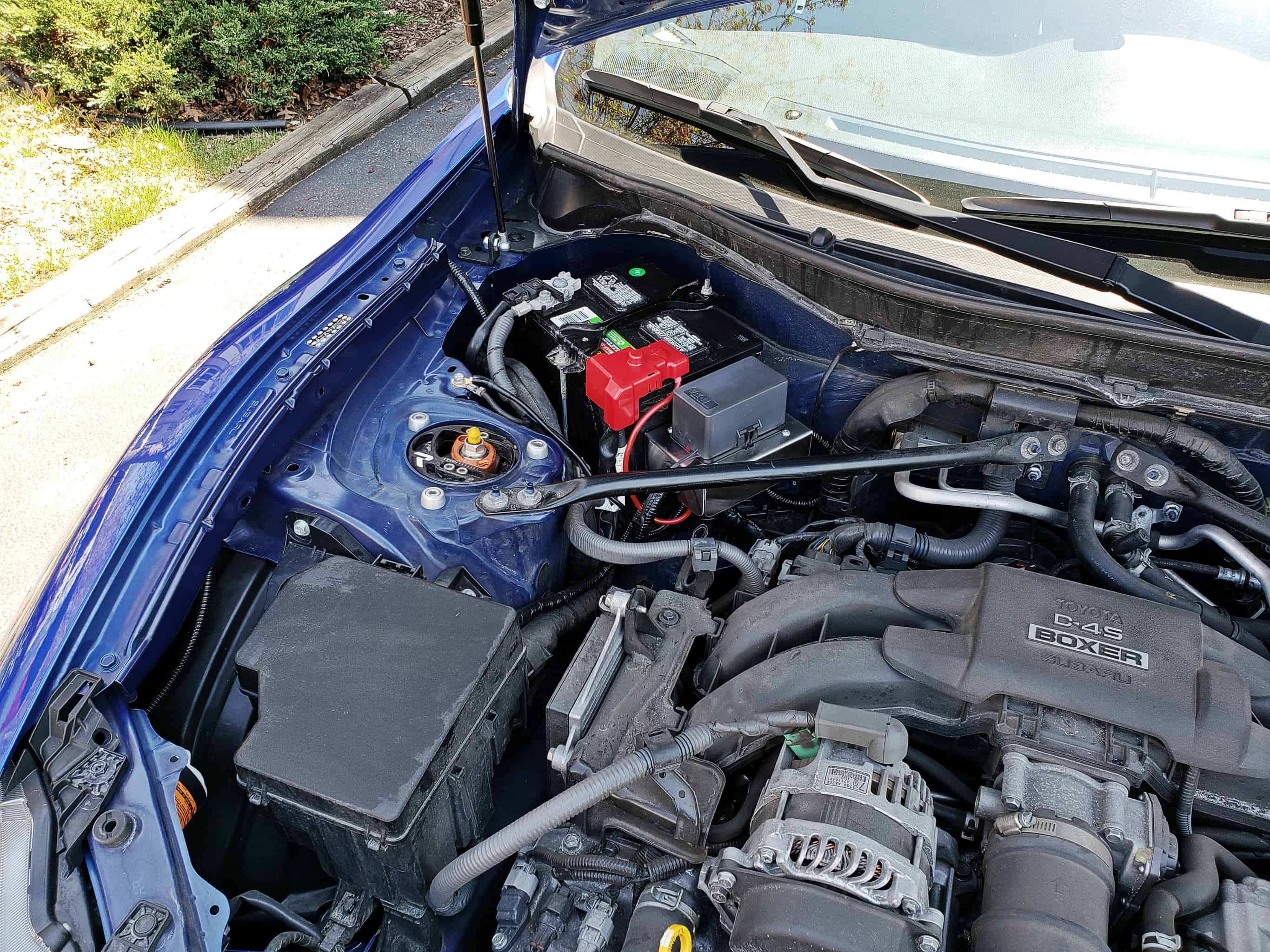 Final Thoughts This was a really fun learning experience for me. I tackled quite a few different things that I’d never done before. I was convinced that the custom trim piece I wanted to make would wind up looking like crap, but my part of the work turn out better than expected, and then the folks at Sweidit really added the finishing touch that took it over the top. At some point I need to figure out how to label the switches (maybe a little aluminum plate that fits over them) but other than that, it looks great. The wiring definitely took a lot of brainstorming ahead of time in order to make sure it was right the first time, and that it all worked as intended. I’m pretty sure it’s all functional. I don’t have all the accessories connected yet, but those that I do appear to be working properly. The Bussmann fuse/relay box is a really cool piece of kit, and makes for a great way to consolidate and organize your wiring. We shall see how reliable it is, but it’s not like it has any moving parts, so I’m not too worried. Overall, a completely successful project, as far as I’m concerned, and everything turned out better than I could have hoped!
__________________
.
 Check out my blog, read all about my BRZ adventures, and oogle my sweet cell-phone photos! You can also find me on Instagram, and on Facebook. Last edited by Stang70Fastback; 05-15-2018 at 01:34 PM. |

|

|
| The Following 13 Users Say Thank You to Stang70Fastback For This Useful Post: | 02.ACCORD.DUDE (05-16-2018), Asidrive (05-07-2018), BirdTRD (05-16-2018), Boomerang (06-06-2020), Brayden_23 (05-15-2018), BRZyJ (05-15-2018), Chimera (05-15-2018), Code Monkey (05-16-2018), jcw99 (08-27-2019), new2subaru (11-30-2019), OfficeWorker (05-17-2018), rvoll (05-06-2018), Suparu (07-08-2020) |
|
05-15-2018, 01:35 PM
|
#2 |
|
A.K.A. Starlord
Join Date: Oct 2013
Drives: 2015 Series.Blue
Location: Illinois
Posts: 1,842
Thanks: 845
Thanked 2,099 Times in 834 Posts
Mentioned: 30 Post(s)
Tagged: 3 Thread(s)
|
Sorry guys. I didn't realize my blog had gone down for a bit right after I posted this. I went ahead and transferred everything into this thread so hopefully y'all can see the entirety of the project now

__________________
.
Check out my blog, read all about my BRZ adventures, and oogle my sweet cell-phone photos! You can also find me on Instagram, and on Facebook. |
|
|
|
|
05-16-2018, 03:17 AM
|
#3 |
|
Member
Join Date: May 2018
Drives: 2017 BRZ PP
Location: NorCal
Posts: 50
Thanks: 4
Thanked 6 Times in 6 Posts
Mentioned: 0 Post(s)
Tagged: 0 Thread(s)
|
That looks awesome!! Would love this in my car.
|
|
|
|
| The Following User Says Thank You to Guest For This Useful Post: | Stang70Fastback (05-16-2018) |
|
05-16-2018, 07:07 PM
|
#4 |
|
Senior Member

Join Date: Nov 2012
Drives: 2015 BRZ Limited
Location: Bay Area, CA
Posts: 487
Thanks: 613
Thanked 269 Times in 181 Posts
Mentioned: 13 Post(s)
Tagged: 0 Thread(s)
|
Beautiful write up! I really love what you did with the wasted space on the push-start panel.
Any chance you made a template of the acrylic piece before setting it in place? No worries if not, seems easy enough to do!
__________________
|
|
|
|
| The Following User Says Thank You to JeremyR For This Useful Post: | Stang70Fastback (05-16-2018) |
|
05-16-2018, 07:23 PM
|
#5 | |
|
A.K.A. Starlord
Join Date: Oct 2013
Drives: 2015 Series.Blue
Location: Illinois
Posts: 1,842
Thanks: 845
Thanked 2,099 Times in 834 Posts
Mentioned: 30 Post(s)
Tagged: 3 Thread(s)
|
Quote:
*gestures vaguely*
__________________
.
Check out my blog, read all about my BRZ adventures, and oogle my sweet cell-phone photos! You can also find me on Instagram, and on Facebook. |
|
|
|
|
| The Following User Says Thank You to Stang70Fastback For This Useful Post: | JeremyR (05-16-2018) |
|
05-16-2018, 07:44 PM
|
#6 | |
|
Senior Member
Join Date: Nov 2012
Drives: 2015 BRZ Limited
Location: Bay Area, CA
Posts: 487
Thanks: 613
Thanked 269 Times in 181 Posts
Mentioned: 13 Post(s)
Tagged: 0 Thread(s)
|
Quote:
 LOL no worries! Seems simple enough i'm just bein lazy 
__________________
|
|
|
|
|
|
05-17-2018, 08:37 AM
|
#7 |
|
A.K.A. Starlord
Join Date: Oct 2013
Drives: 2015 Series.Blue
Location: Illinois
Posts: 1,842
Thanks: 845
Thanked 2,099 Times in 834 Posts
Mentioned: 30 Post(s)
Tagged: 3 Thread(s)
|
Haha. Good luck sir! It's pretty simple once you get it shaped properly. The cutout not being symmetrical is kind of a PITA.
__________________
.
Check out my blog, read all about my BRZ adventures, and oogle my sweet cell-phone photos! You can also find me on Instagram, and on Facebook. |
|
|
|
|
10-12-2018, 07:32 AM
|
#9 | |
|
A.K.A. Starlord
Join Date: Oct 2013
Drives: 2015 Series.Blue
Location: Illinois
Posts: 1,842
Thanks: 845
Thanked 2,099 Times in 834 Posts
Mentioned: 30 Post(s)
Tagged: 3 Thread(s)
|
Quote:
[ame]https://www.youtube.com/watch?v=UjkKfxSaf8M[/ame]
__________________
.
Check out my blog, read all about my BRZ adventures, and oogle my sweet cell-phone photos! You can also find me on Instagram, and on Facebook. |
|
|
|
|
|
10-13-2018, 12:04 AM
|
#10 |
|
Member
Join Date: Sep 2017
Drives: Car Collector
Location: Pacific NW
Posts: 76
Thanks: 26
Thanked 35 Times in 17 Posts
Mentioned: 0 Post(s)
Tagged: 0 Thread(s)
|
Amazing !!!
A neighbor has these horns in his large 4x4 truck and they instantly have you looking for train tracks. i can not imagine the effect you have coming from something that all those around you feel can not possibly be the source.
Amazing work Sir |
|
|
|
| The Following User Says Thank You to CraigVM For This Useful Post: | Stang70Fastback (10-15-2018) |
|
08-26-2019, 03:15 PM
|
#11 |
|
A.K.A. Starlord
Join Date: Oct 2013
Drives: 2015 Series.Blue
Location: Illinois
Posts: 1,842
Thanks: 845
Thanked 2,099 Times in 834 Posts
Mentioned: 30 Post(s)
Tagged: 3 Thread(s)
|
If anyone wants some toggle switches for their center console, I've since begun selling 3D printed toggle switch inserts after people saw this post and expressed interest. I have created a post here:
http://www.ft86club.com/forums/showthread.php?p=3251659
__________________
.
Check out my blog, read all about my BRZ adventures, and oogle my sweet cell-phone photos! You can also find me on Instagram, and on Facebook. |
|
|
|
|
|
|
|
|
|
|
 Similar Threads
|
||||
| Thread | Thread Starter | Forum | Replies | Last Post |
| Toggle switch under driver dash | Drifting86 | Electronics | Audio | NAV | Infotainment | 8 | 01-01-2016 07:57 PM |
| Auxiliary Switches | boredom.is.me | Cosmetic Modification (Interior/Exterior/Lighting) | 21 | 07-27-2014 05:38 AM |
| Necessary to toggle between 2-3rd gear at autox? | foursix86 | Tracking / Autocross / HPDE / Drifting | 3 | 08-28-2013 08:06 AM |
| Does anyone know where I can get switches for led? | Minovsky | CANADA | 12 | 08-24-2013 09:25 PM |
| 12v RCA Switch/Toggle? | MmmDieselFumes | Electronics | Audio | NAV | Infotainment | 23 | 08-13-2013 11:05 PM |


