


|
||||||
| DIY (Do-It-Yourself) Guides For all DIYs. |
 |
|
|
Thread Tools | Search this Thread |
 01-27-2014, 03:43 PM
|
#1 |
|
Senior Member

Join Date: Jun 2012
Drives: 13 CSB BRZ Ltd
Location: United States
Posts: 1,035
Thanks: 147
Thanked 530 Times in 286 Posts
Mentioned: 39 Post(s)
Tagged: 0 Thread(s)
|
DIY - BRZ Boomerangs - Brighter, Better
Disclaimer: This tutorial requires proficiency with a soldering iron. I am not responsible for any damage you or these instructions cause to your vehicle. Proceed at your own risk. This tutorial assumes you are already planning to open your headlights. I would recommend having all the necessary parts and tools in hand before disassembling your headlights. And the most important thing, READ THE ENTIRE TUTORIAL BEFORE BEGINNING!
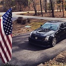
Parts List 4x 25mm Square x 15mm High Alpha Heat Sink - 15.6 °C/W 2x 700mA, Externally Dimmable, FlexBlock Wide Range DC Driver - With Leads 1x Arctic Silver Low Thermal Resistance Adhesive Tools Needed Exacto or Hobby Knife Soldering Iron with a conical tip - 20W to 30W is plenty Solder - Pb free is always preferable, smaller gauge is easier to work with Disposable plastic plate or cardboard to mix thermal epoxy on Disposable plastic silverware or something to mix epoxy with Wire cutters Wire strippers Double sided adhesive strips/tape - DO NOT SKIMP ON THESE - can be found at home depot or any autoparts store Digital Multimeter - to test for continuity Ever since I first saw the BRZ running lights on with the DRLs, I hated it and wondered why Subaru didn't make them brighter. I wanted the boomerangs to be just as bright as the DRLs, or close to it. This tutorial properly addresses this issue, electrically and thermally. The boomerangs are lit up by two Luxeon Rebel Neutral White LEDs. These LEDs are designed to be "driven" at 700mA typically and even up to 1000mA with the proper thermal management. From the factory, these LEDs aren't driven at all. That term typically means there is control circuitry acting as a current source to the LEDs. This means that no matter what the input voltage to the controller is, the controller maintains the proper amount of current going to the LEDs. This is the schematic for the stock circuit.  The stock circuit has nothing like a proper current source. It's much more simple and therefore much cheaper to manufacture. At 12.7v source voltage, the circuit pulls 154mA through each LED. The equivalent resistance of the parallel resistor circuit is 39 ohms. The dual capacitors in parallel with the Zener diode in reverse bias function as a pseudo-voltage regulator. The makes the boomerangs much less susceptible to dimming from voltage drops related to drops in engine idle rpm. The DRLs are really bad about this because there is no control circuitry or capacitor/Zener diode circuit on them. If you ever park your BRZ close to and facing a wall, keep your foot on the brake while slowly letting the clutch out, just enough to drop the engine rpm slightly, you'll see the DRLs dim, or even turn off. The boomerangs won't do this because of this circuit. Because these LEDs are running at 154mA, they require zero thermal management. Luxeon provides recommended board layout and solder masking files freely on their website. This layout has "vias" in the board which are basically plated thru-holes. They help draw some of the heat away from the LED and dissipate it to the air. Running at such low current, these vias are all the LEDs need to remain cool. Once you start increasing the current to the LEDs, thermal management (read Heatsinks) is needed.  Let's start by addressing what changes need to be made to the stock circuit boards. You are basically rewiring the circuit boards to accommodate the current driver and getting rid of unnecessary components. I'm assuming you have already disassembled the headlights and you have the this piece sitting in front of you.  Step 1: Remove the 3 screws that hold the boards to the plastic piece. Step 2: Cut the white wire at the red X, cut the red wire at the red x, and throw away the board with the huge resistors.  Step 3: Take the soldering iron and heat up one side of the Zener Diode. It should be marked "ZNR" on the board. Heat up one side and lift up with the soldering iron. Your goal is to lift the contact up off the board. When you have one contact separated, apply the soldering iron to the other contact. This should free the Zener diode from the board. Throw it away. Step 4: Apply a good amount of new solder to the pads where the Zener diode used to sit. You will be soldering two wires directly to these pads. Step 5: This is very very tricky so please take care as to which part of the board you are scoring. I'll start the description referencing the driver side headlight, but you can start with whichever side. You now need to "break" the copper trace leading from the negative side of the LED. In the following picture, you should see a red line directly in front of the blue wire. You need to take an exacto knife and SCORE the board, breaking the trace. This does take a good amount of pressure. Go slowly, and be very controlled. You do not want the blade to jump off the trace cutting something else on the board or yourself. After you cut the copper trace coming from the negative side (which is marked by the - symbols on the board) you need to check with the Digital Multimeter to make sure the now separate traces are no longer connected. If you do not ensure they DO NOT make contact, you will fry the LED as soon as you apply power. For the passenger side, do the same for both of the red lines. Score the board with the exacto knife until you are under the copper layer and well into the board material. Check for continuity and ensure there is none. A comment from @Beebe "The only thing I would clarify on is the exact trace to cut on the passenger side. The picture was a little deceiving with the red line. Cut the top most trace pictured (which the blue wire is laying atop of), as well as the trace on the right side of the board as pictured." A comment from @marcoaferrer "When your soldering the blue wire onto the trace BE SUPER CAREFUL. If you apply too much heat youll lift the trace. You also want to expose enough of the trace so that you have a good seat for your wire. After the blue wire is soldered, baby it so you dont damage the trace and pull it off the board." Driver Side  Passenger Side  Step 6: Now, you need to remove the white layer on top of the board in certain spots to be able to reconnect to the LEDs. This white layer is called the solder mask. You will need to take an exacto/hobby knife and lightly scrape the solder mask off until you see nice shiny bare copper. Take care to not scrape deeply into the copper. You are basically creating a new soldering pad on which you will solder the wires coming directly from the current source, so you will need a good amount of bare exposed copper. Refer to the above two photos. In the area you see the blue wire soldered, you need to expose that much copper. Do not scrape off the solder mask on adjacent copper layers! Step 7: You will need to cut off one of the old supports for the resistor board so that the LED driver will lay flat on the assembly. I don't have any photos, but it is the plastic support in this photo circled in red.  Step 8: I will start by showing a photo of what you want your end result to look like. On the left is the modified assembly, on the right is the stock assembly. You will need to lay the board and current source in place on the plastic piece to determine how much of the leads coming from the LED Driver you will need to cut.  Once you figure out the correct wire lengths, strip the blue, red, white, and black wires. Cut the purple and gray wires completely off. You will not need them as you are not going to be dimming the LEDs. Step 9: I highly recommend twisting the ends of the stripped wires to ensure you have no fraying or stray strands. Tin the tips of the black, red and blue wires. Referring to the photos in Step 5, solder the red, black, and blue leads on to the correct pads on the corresponding sides. This should be clear from the photos. Step 10: Place the newly soldered LED driver and remaining 2 boards back on the plastic assembly. You should now have the white wire from the LED driver and the red wire from the second LED board free. Cut them down to the correct length, place a small piece of heat shrink tubing over one, twist them together, solder, and apply heat to the heatshrink over the exposed wires. It should look like this when completed.  Step 11: Now that the electrical part is finished, set the boards on the plastic assembly and screw them into place. Apply enough strips of the double sided adhesive to the back of the LED driver to cover it well, and press it into it's final position on the assembly. Step 12: Now you need to secure the heat sinks onto the boards. Take the two-part thermal epoxy and measure out equal parts. There is a video on the purchase website that I recommend watching. Mix the epoxy and apply it to the bottom of the heatsinks. Set the heat sinks on each board in the same places as shown below. Press firmly for at least 30 seconds. Allow the epoxy to fully set. A comment from @marcoaferrer Also when you glue on the heat sink to the board with the blue wire, your going to want the fins facing vertical. This makes it a whole lot easier the dremel the fins down so they fit in the housing. let me see if i can dig up a picture so i can explain it better. And the final product:   Step 13: When remounting the entire assembly to the headlight housing, there won't be enough clearance for one of the heatsinks on each side. You will need to trim some of the fins down in order for the entire assembly to sit flush on the mounts. Be conservative when clipping some of the fins down as you only want to take off just enough to allow the assembly to sit flush. The more material you remove from the heatsinks, the hotter the LED is going to run which diminishes the LEDs life. Results:   You're finished! Now do the other side... EDIT: 4/12/14 Here are some crappy side by side photos of my car with a stock BRZ boomerang. Sorry for the iPhone camera.   Completed comments from @Beebe "A few of us Houston 86 guys accomplished this mod last Sunday (8/3) on two cars with great success, in about 6hrs for both. We did a group buy on the parts listed to save on shipping so the mod only really cost us around $76ea. " Last edited by Acree; 08-07-2014 at 11:39 AM. |

|

|
| The Following 22 Users Say Thank You to Acree For This Useful Post: | caffeinejunky (02-05-2014), Choco (01-21-2015), disgruntld (01-30-2014), djdnz (02-17-2014), DocWalt (05-24-2014), DoomsdayJesus (04-28-2014), ericmpena (04-12-2014), eromsdal (03-28-2017), GaN-MaN (03-12-2014), JFBRZ711 (03-21-2014), JPxM0Dz (02-05-2014), mmontes (02-11-2014), Mooseknuckle44 (04-28-2014), ShoNUFF (03-21-2014), SirBrass (01-27-2014), sirisvirus (04-05-2014), spdfreak (04-29-2014), ToyoburuBRZ (01-27-2014), Tyrant (01-27-2014), woode (06-12-2014), WRXGuy1 (04-22-2014), xkalelx (10-05-2015) |
|
01-27-2014, 04:15 PM
|
#2 |
|
Senior Member

Join Date: Jun 2013
Drives: Whiteout FRS, Audi A4, 135i (sold)
Location: Fayetteville, NC
Posts: 918
Thanks: 1,440
Thanked 567 Times in 289 Posts
Mentioned: 11 Post(s)
Tagged: 0 Thread(s)
|
Nice, great DIY. Looks like some of the pictures are broken though?
__________________
boooooooooooooooooost
|
|
|
|
|
01-27-2014, 04:23 PM
|
#3 |
|
Trust me, I'm the Doctor

Join Date: Nov 2013
Drives: 2019 WRX Limited (WRB)
Location: North East PA
Posts: 2,723
Thanks: 4,304
Thanked 1,251 Times in 781 Posts
Mentioned: 33 Post(s)
Tagged: 1 Thread(s)
|
DIY text is excellent, but most of the image links are broken. Maybe consider doing direct attachment, instead of image hosting?
Edit: the broken images aren't hosted, they're attached via the forum. I tried doing "Open image in separate tab", and the result was "invalid attachment specified." So, perhaps these images were somehow deleted?
__________________
Subies Of Blessed Memory: '05 Forester, '08 WRX, '13 STi
Daily Driver: 2014 BRZ 6MT Limited  ^GT5 Replay Photo Mode^ Last edited by SirBrass; 01-27-2014 at 04:38 PM. |
|
|
|
|
01-27-2014, 04:38 PM
|
#4 |
|
Senior Member
Join Date: Nov 2011
Drives: Subaru BRZ Limited 6MT
Location: Winston-Salem, NC
Posts: 2,432
Thanks: 712
Thanked 954 Times in 545 Posts
Mentioned: 47 Post(s)
Tagged: 0 Thread(s)
|
I switched over to imgur for pic hosting, super easy and no problems.
__________________
Innovate Supercharged Black Limited BRZ 6-Speed MT(Build Thread)
2010 Cadillac CTS-V Sedan M6 w/550whp (Build Thread)  |
|
|
|
|
01-27-2014, 04:41 PM
|
#5 |
|
Senior Member
Join Date: Jun 2012
Drives: 13 CSB BRZ Ltd
Location: United States
Posts: 1,035
Thanks: 147
Thanked 530 Times in 286 Posts
Mentioned: 39 Post(s)
Tagged: 0 Thread(s)
|
Moved to imgur for hosting.
|
|
|
|
|
01-27-2014, 04:42 PM
|
#6 |
|
Senior Member
Join Date: Jun 2012
Drives: 13 CSB BRZ Ltd
Location: United States
Posts: 1,035
Thanks: 147
Thanked 530 Times in 286 Posts
Mentioned: 39 Post(s)
Tagged: 0 Thread(s)
|
Let me know if they don't show up now.
|
|
|
|
|
01-27-2014, 04:47 PM
|
#7 | |
|
Trust me, I'm the Doctor
Join Date: Nov 2013
Drives: 2019 WRX Limited (WRB)
Location: North East PA
Posts: 2,723
Thanks: 4,304
Thanked 1,251 Times in 781 Posts
Mentioned: 33 Post(s)
Tagged: 1 Thread(s)
|
Quote:

__________________
Subies Of Blessed Memory: '05 Forester, '08 WRX, '13 STi
Daily Driver: 2014 BRZ 6MT Limited ^GT5 Replay Photo Mode^ |
|
|
|
|
|
01-27-2014, 04:50 PM
|
#8 |
|
I love peanut butter
Join Date: Jun 2013
Drives: 2013 SWP BRZ Limited
Location: NJ
Posts: 1,598
Thanks: 428
Thanked 584 Times in 349 Posts
Mentioned: 14 Post(s)
Tagged: 2 Thread(s)
|
Looks great and nice diy, do you have any pics of them reinstalled in the car, preferably next to a stock BRZ?
|
|
|
|
|
01-27-2014, 04:51 PM
|
#9 | |
|
Senior Member
Join Date: Jun 2012
Drives: 13 CSB BRZ Ltd
Location: United States
Posts: 1,035
Thanks: 147
Thanked 530 Times in 286 Posts
Mentioned: 39 Post(s)
Tagged: 0 Thread(s)
|
Quote:
|
|
|
|
|
| The Following User Says Thank You to Acree For This Useful Post: | Sportsguy83 (05-11-2014) |
|
01-27-2014, 05:42 PM
|
#10 | |
|
Junior Member

Join Date: Oct 2012
Drives: Gray.
Location: VA.gina
Posts: 1,937
Thanks: 3,620
Thanked 2,086 Times in 995 Posts
Mentioned: 67 Post(s)
Tagged: 1 Thread(s)
|
This looks great! Good write up too!
__________________
Quote:
|
|
|
|
|
| The Following User Says Thank You to IloveBaldEagles For This Useful Post: | Sportsguy83 (05-11-2014) |
|
01-27-2014, 06:06 PM
|
#11 |
|
GBS Mafia Member

Join Date: Apr 2013
Drives: with Snow mode on
Location: Costa Mesa
Posts: 541
Thanks: 338
Thanked 312 Times in 158 Posts
Mentioned: 8 Post(s)
Tagged: 0 Thread(s)
|
Someone please take my money. I feel as if I'm a klutz when it comes to electrical wiring. I'm very impressed by this DIY, but having no electrical background whatsoever, I'm hesitant to even take out the headlights. However, this would be something really cool to bring into an auto electrical shop and see if they could have at it. Subbed for pics!
__________________
 GBS Mafia |
|
|
|
|
01-30-2014, 07:19 PM
|
#12 |
|
Less than pleased...

Join Date: Dec 2012
Drives: '13 BRZ Ltd SSM 6MT
Location: Newport News, VA
Posts: 280
Thanks: 125
Thanked 96 Times in 73 Posts
Mentioned: 22 Post(s)
Tagged: 3 Thread(s)
|
I'm with this ^ guy. Great write up, I'm glad somebody has the tech knowledge to figure this out, but I hardly trusted myself to go my Hella horns and that was just a few wires.
__________________
 |
|
|
|
|
01-30-2014, 07:22 PM
|
#13 |
|
Senior Member
Join Date: Jun 2012
Drives: 13 CSB BRZ Ltd
Location: United States
Posts: 1,035
Thanks: 147
Thanked 530 Times in 286 Posts
Mentioned: 39 Post(s)
Tagged: 0 Thread(s)
|
I can do this for you guys, but you have to ship me the pieces from your headlights.
__________________
2011 BMW M3 (No torque dip)
2013 Subaru BRZ - SOLD - Build Thread |
|
|
|
| The Following User Says Thank You to Acree For This Useful Post: | Sportsguy83 (05-11-2014) |
|
01-30-2014, 07:30 PM
|
#14 | |
|
Never on Time Always Late

Join Date: Jun 2012
Drives: #silenced crickets
Location: Norcal
Posts: 578
Thanks: 86
Thanked 152 Times in 101 Posts
Mentioned: 9 Post(s)
Tagged: 0 Thread(s)
|
Quote:
Come on BRZhood.. Unite for the brite!
__________________
CO>CA Cartel
|
|
|
|
|
|
|
|
|
|
|
|
 Similar Threads
|
||||
| Thread | Thread Starter | Forum | Replies | Last Post |
| brighter fog light bulb for BRZ? | chenshuo | Cosmetic Modification (Interior/Exterior/Lighting) | 17 | 01-11-2016 01:57 AM |
| Interior LED Dome Light Diffuser | DIY | 6X Brighter | Dezoris | Cosmetic Modification (Interior/Exterior/Lighting) | 8 | 04-21-2013 08:59 PM |
| Brighter "Boomerangs" | Jaylyons1 | Mid-Atlantic | 3 | 02-05-2013 07:53 PM |


 2013 Subaru BRZ Limited
 The Tin Can
 Ms. Gunny