


|
||||||
| Forced Induction Turbo, Supercharger, Methanol, Nitrous |
 |
|
|
Thread Tools | Search this Thread |
 05-22-2016, 01:38 PM
|
#15 |
|
Fidei Defensor
Join Date: Mar 2016
Drives: 2015 Subaru BRZ Limited - Black
Location: Sequim
Posts: 34
Thanks: 1
Thanked 3 Times in 1 Post
Mentioned: 0 Post(s)
Tagged: 0 Thread(s)
|
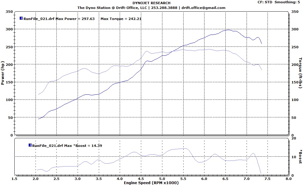
Still waiting on the boost curve.
I wanted to add one thing I remembered this morning though, I think it was mentioned to me that the tune couldn't be completed via the MAF, and so was done via speed density or something like that. Could this have affected my results? |

|

|
|
05-22-2016, 05:53 PM
|
#16 | |
|
Senior Member
Join Date: Aug 2014
Drives: '14 981CS, '99 NB1
Location: Oregon
Posts: 1,274
Thanks: 1,234
Thanked 1,201 Times in 631 Posts
Mentioned: 114 Post(s)
Tagged: 2 Thread(s)
|
Quote:
|
|
|
|
|
|
05-22-2016, 10:41 PM
|
#17 | |
|
...Just add nauseum

Join Date: Jan 2015
Drives: 2003 (AP1) S2000
Location: Miami, FL
Posts: 545
Thanks: 310
Thanked 784 Times in 335 Posts
Mentioned: 19 Post(s)
Tagged: 1 Thread(s)
|
Quote:
Second. Wow. Time for a new tuner. That's a big fat crock of sh*t. (If that is indeed what he said.. If not, benefit of the doubt for things lost in translation. Whatever.) Let me give you a quick (simplified) background. The MAF sensor is an ingenious device that uses a hot piece of wire to translate the mass of air passing the sensor, and entering the engine, to a voltage signal with a range of 0 to 5 volts. The ECU uses a primary table, and a series of corrective tables, to determine how much fuel to deliver, based on the mass of air entering the engine. Say you turbocharge the engine. The mass of air passing the MAF sensor dramatically increases, and you get to use more of the voltage range of the sensor. Problem is, eventually you can flow so much air that you hit the limit of the sensor and keep right on going. OH NO! How do you figure out how much fuel to deliver? More on that soon. The limit of the sensor is somewhat affected by the diameter of the pipe in which it sits, but suffice to say you're not going to be anywhere close to the limit of that sensor at 7 PSI on a GTX 2-anything. Ptuning's turbo kit has a perfectly good MAF housing. On a cold (like, snow cold) day, you might hit 5V at 10 PSI. Basically, it's bullsh*t to say it "can't" be tuned on MAF. This is why you need a new tuner. An honest one would explain the seemingly arbitrary switch to Speed/Density. Ok, back to SD. One suitable alternative to MAF'ing it is called "Speed / Density" tuning. Using the Ideal Gas Law PV = nRT* a table**, and some sensors*** we can determine the amount of air entering the engine, and figure out how much fuel to deliver. That simple. That said, your torque curve looks suspiciously like a magnified version of the OEM curve. That troubles me. Footnotes: * PV= nRT (Pressure x Volume = [amount of gas (mass, in moles.)] x [universal gas constant] x [Temperature] ** The table has the independent (measurable) variables on the axes, and uses these to look up the (experimentally determined) dependent variable. That variable is Volumetric Efficiency. More on this to come. *** The sensors are Manifold absolute Pressure (MAP) and Intake Air Temperature (IAT) OK. "Volumetric Efficiency" ... Big words. We want to determine the amount (mass) of gas entering the engine. From this, we can deliver an appropriate amount (mass) of fuel for the desired air-fuel ratio. Simple then, we solve the Ideal Gas equation for "n." Reading the Ideal Gas Law, one can surmise that if we know pressure and temperature from sensors, and the gas constant from a textbook, the only missing variable is volume. AHA! We know that our 4-stroke, 2-liter engine theoretically displaces 1 liter of air per rev. This is where VE comes in. The 2 intake strokes per 360 crankshaft degrees sweep a 1 liter area, and pull some air through the intake valves. We know the density of the air in the intake manifold from MAP and IAT. "Volumetric Efficiency" is the ratio of the density in the manifold to the final density in the cylinder when the intake stroke is finished. Lots of complex variables affect this ratio, and it varies with RPM. Rather than try to solve for all of them at all times, (this is not practical for many reasons) we simply say for this rpm, (SPEED) on one axis, and this air density, (DENSITY) on the other, the Volumetric Efficiency is X. There's your table. The table is determined experimentally, and then largely left alone, unless a relevant component of the intake or exhaust system is changed. Now you know how much air is there, you can accurately deliver fuel. That said, you can figure out if SD did indeed negatively affect your tune by doing the following: Log commanded AFR, and compare it to actual (observed) AFR on a wideband sensor (there's a wideband on every dyno.) If the difference between the two is minor, the SD tuning has been done correctly, and is not to blame. That said, your AFR's could be far from ideal, but if they're accurate to command, the VE table is accurate, and you can cross that off the list of potential problems..
__________________
Inline 4 is best 4
There are many ways to displace. -Spartarus |
|
|
|
|
|
05-23-2016, 10:02 AM
|
#18 | |
|
Join Date: Jun 2013
Drives: '92 Nissan 240sx KA-T
Location: Manassas, VA
Posts: 105
Thanks: 25
Thanked 31 Times in 23 Posts
Mentioned: 2 Post(s)
Tagged: 0 Thread(s)
 |
Quote:
EcuTek specifically implements a transition from MAF to SD based on various parameters such as load, RPM, etc. It's not a hard switch either but works to blend the two together to smoothly transition between the two. You can set it as low or as high as you want. We generally run these vehicles MAF until around 4.5V where we'll transition to SD but this will only happen in boost. |
|
|
|
|
|
05-23-2016, 06:08 PM
|
#19 | |
|
Senior Member
Join Date: May 2014
Drives: Built FA20
Location: Toledo, OH
Posts: 125
Thanks: 28
Thanked 49 Times in 21 Posts
Mentioned: 0 Post(s)
Tagged: 0 Thread(s)
|
Quote:
|
|
|
|
|
|
05-25-2016, 07:52 PM
|
#20 |
|
Fidei Defensor
Join Date: Mar 2016
Drives: 2015 Subaru BRZ Limited - Black
Location: Sequim
Posts: 34
Thanks: 1
Thanked 3 Times in 1 Post
Mentioned: 0 Post(s)
Tagged: 0 Thread(s)
|
Here's my boost curve. I'm not sure why, but this isn't the final tune I was sent a chart for a couple weeks ago. This appears to be the 21st run, whereas what I was sent a couple weeks back is the 12th. It's possible when they were done running a bunch of pulls, they decided the 12th run was the best balanced of whatever criteria they had in mind. Anyway, here's the 21st run's boost curve:
|
|
|
|
|
05-25-2016, 09:46 PM
|
#21 | |
|
Senior Member
Join Date: Oct 2014
Drives: '15 FRS
Location: Oregon
Posts: 221
Thanks: 8
Thanked 280 Times in 127 Posts
Mentioned: 42 Post(s)
Tagged: 1 Thread(s)
|
Quote:
@ptuning, we've never had a problem doing reflashes to test cam phasing changes in house on our Dynapack. the 90 seconds it takes to do a reflash is, if anything, perfect for cooldown time between pulls as long as you monitor engine operating parameters between pulls. I can do a pull, wait 20 minutes, bring the engine back to previous operating conditions and do another pull... graphs will be almost identical if I made zero changes to the tune... When I first dropped our MoTeC programming into our shop FRS I verified cam timing since the ECU is all "live" and it was dead on within ~2 degrees of what I had found using ECUTek on the stock ECU, even doing quick live tuning updates with the MoTeC. Power with the MoTeC was identical to the stock ECU when the car had bolt ons (not surprising... it was just bolt ons). |
|
|
|
|
|
|
|
|
|
|
|
 Similar Threads
|
||||
| Thread | Thread Starter | Forum | Replies | Last Post |
| Digital boost gauge w/ vent pod grim speed boost controller | Meetjoeblack | Engine, Exhaust, Bolt-Ons | 0 | 03-09-2015 01:27 PM |
| Detailing steps? | nickmerronesucks | Cosmetic Maintenance (Wash, Wax, Detailing, Body Repairs) | 10 | 03-01-2015 09:35 PM |
| Our first steps in drifting an automatic FRS | imartisfrs | Scion FR-S / Toyota 86 GT86 General Forum | 1 | 12-14-2014 02:54 AM |
| Took car out of the dealership, what are the recommended steps? wax , seal, etc. | dssence | Cosmetic Maintenance (Wash, Wax, Detailing, Body Repairs) | 12 | 02-26-2014 03:14 AM |


