 02-23-2015, 09:31 PM
|
#1
|
|
Senior Member
Join Date: May 2014
Drives: 2014 Scion FR-S Monogram
Location: Saskatoon
Posts: 216
Thanks: 54
Thanked 126 Times in 67 Posts
Mentioned: 4 Post(s)
Tagged: 0 Thread(s)
|
Switched DRL Strip(Monogram/GT86 Headlights) With Pictures
Intro: One of the main reasons I purchased my Monogram FR-S was because of the headlights. I loved how aggressive the LED strip looked, almost like angry eyebrows. My only complaint was that they could not be on at the same time as the projectors. Well with this DIY you can change that!
Purpose: To be able to have the DRL LED strip illuminated at the same time as your low beam/high beam projectors.
Overview: Install a switched ground on the DRL wire running into the BCM. The BCM acts as a ground for when the DRL's should come on, so if you install a ground before the BCM you will be able to switch the LED strip on and off.
Supplies Required:
1) A button/switch(12V)
2) As much wire(between 16 and 22 gauge) as you need to have your switch mounted where you would like
3) A diode
4) Grounding ring terminal
Time Required: +/= 45 minutes
Tools Required:
1) Phillips Head Screwdriver
2) Soldering Iron/solder
3) Wire strippers/cutters
4) Whatever tools you need to mount the switch of your choice
5) Wire crimpers
Directions:
1) First step is to remove the panel under the steering wheel which houses the trunk, headlight aiming, interior light dimmer and, in my case, the fog light switch. Do this by removing the trim panel covering the fuses by the driver door, and remove the screw revealed under this panel. There is also a screw under the panel near the center console which will need to be removed as well. Once the 2 screws are removed pull back on the panel and release the clips holding it in place. Disconnect any electrical connections and set panel aside.
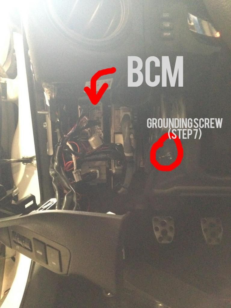
2) Locate the BCM now that the panel is removed. It is located near the driver door.(See picture)
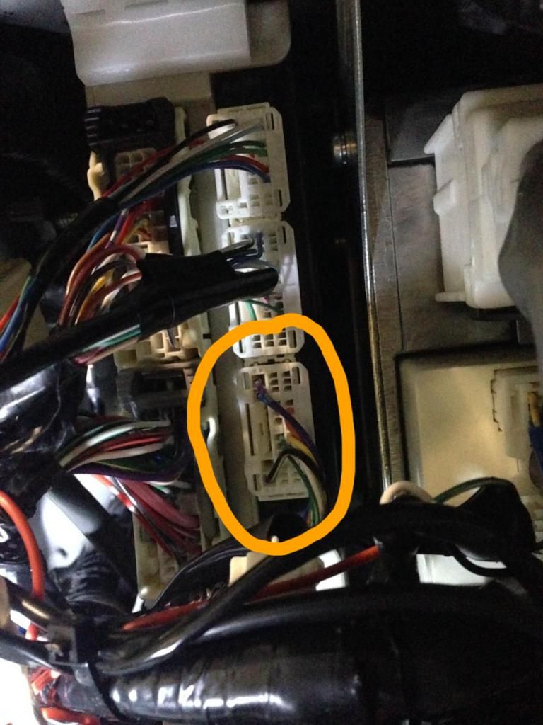
3) Locate and remove the BCM connector which houses the DRL wire. The orange wire is the DRL ground wire and is the wire we will be modifying. (See picture)
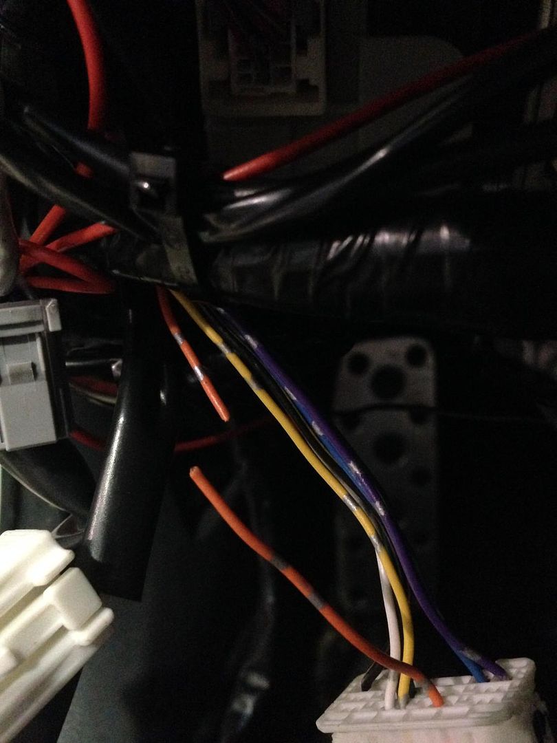
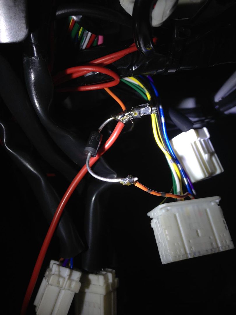
4) Remove some insulation and electrical tape to gain more access to the orange wire as necessary. Cut the wire half way to make soldering easy as possible. Strip away wire insulation as much as you need and expose the bare wire.
5) Prepare the wire you will be connecting to the POWER side of the switch, known as the power wire from here on. Strip some insulation and expose the bare wire.
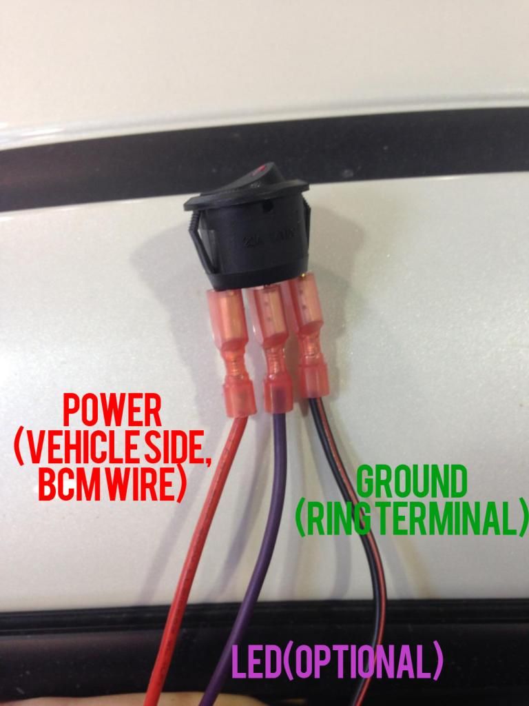
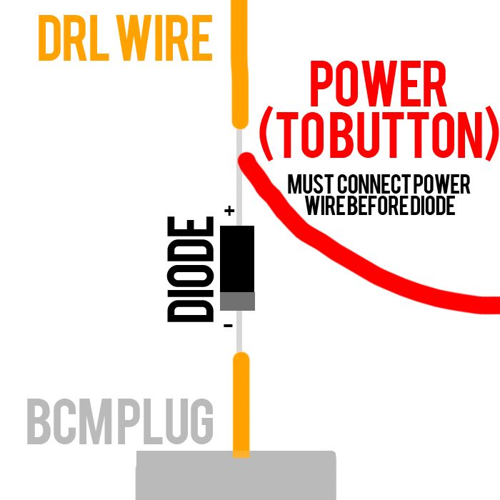
6) Solder the positive side of the diode, the power wire and the vehicle side of the orange DRL BCM wire together. The diode will not allow ground ground to go into the BCM, protecting from possible codes as well as giving electricity only one path. Also solder the negative side of the diode to the connector side of the BCM DRL wire. (See diagram)
7) Prepare your wire which will connect to the GROUND side of the switch(ground wire). Attatch one side to the grounding ring terminal, and the other side will attatch to the switch. I used crimping terminals to attatch the wires to my button switch. Remove the screw near the steering wheel(See picture in step 2) and connect the grounding ring.
8) Cover your soldering connections with shrink wrap or electrical tape and connect the BCM connector back into the BCM. Connect your wires to the switch. Start your car and give it a test! If all works you should be able to turn your DRL LED's on and off as you wish, even when the projectors are on!
9) Mount your switch however and wherever you want, and reinstall the panel. You're all done!
NOTE) My button had an LED prong, which not all will have and is unneccessary if you do not want. I tapped into the switch wire from the Spyder foglights to power the LED.
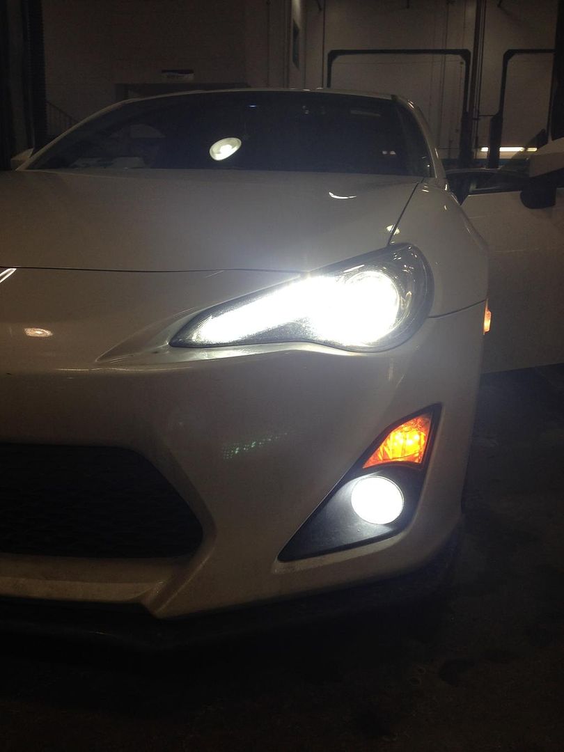
Final Result:
|

|

|